How To Wire A Backup Battery IgnitionAn alternate system For Your 1955-69 BMW Twin |
|
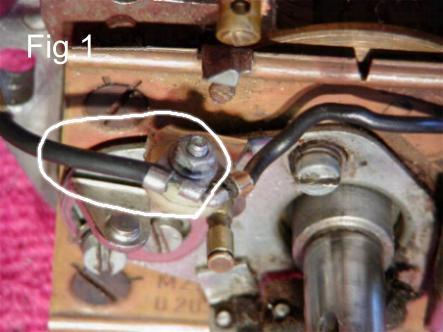
Beginning in the early 1980s, I began to experience intermittent starting problems with my early series bike. At first it was only a little irritation, an occasional difficulty in starting the bike after it had warmed up. With time, the problem progressed to the point that it was impossible to start the bike anytime it had been warmed up. Eventually the coil died, and I was left to push the bike home, or call for help, a very un-BMW like thing to have to do. Diagnosis of this problem is easy today, I know that the problem is coil failure. When the above symptoms first start, I just replace the coil. There is an additional problem however, that is that the new replacement coils that are available, are for the most part, not very reliable, I have had several fail on me. My wonderful BMW, the bike that had taken me so many places, some places so remote there wasn?t another person for miles and miles, the bike that had never missed a beat, now couldn?t be counted upon to get me to the store and back, something needed to be done. At first I converted to a battery ignition system, however that proved to be not quite the cure I had hoped for. A dead battery one evening when I was leaving work showed me the shortcomings of a battery only ignition, when you have a 6-volt system, I couldn?t get a jump, and I couldn?t push start it. It was my dislike for the loss in reliability that was the inspiration for my designing this backup battery ignition system. This system is really the best of both worlds, the magneto for general use, and the battery system for when the magneto coil fails. These instructions are for a bike with a 6-volt electrical system, and no difficult to dismount fairing. If you have converted to a 12-volt system, or you have a complex, difficult to dismount fairing, you will need to make the necessary changes. You will need the following items. 1) A suitable 6-volt dual output ignition coil, with high-tension leads, and spark plug connectors. 2) Insulated hook up wire in two different colors, for ease of instruction, we will use red and black, you will need more of the red than the black, and this will be explained in the text. Hook up wire is the name of the insulated general-purpose wire that is available at auto parts stores, 14 ga. is big enough. 3) Two wire nuts, gray. Wire nuts are color coded for size, gray is correct for 14 ga. wire. 4) Some zip-ties, and electrical tape, 5) Some electrical lugs, ring lugs are preferred, but fork lugs will work. If you have the equipment, knowledge, and skill to solder, use solder lugs, otherwise crimp lugs will do. 6) Some method to mount the coil. Mounting requirements will vary depending upon the coil that you choose. If you use a Harley 6-volt coil, you can simply zip-tie it to the top frame rail with some foam sandwiched between the coil and the frame for padding. The pictures provided show a Dyna coil mounted. 7) Some basic understanding of how to make electrical connections. Lets get to workThese photographs are shown on parts of a /2, not a whole bike. This should help you see the details, but will require some familiarity with the bike. 1. Start by removing the engine front cover, gas tank, and the headlight glass/ring assembly from the headlight shell, but do not remove the headlight shell from the bike. 2. Locate the black wire that runs from the coil to the points. There should be a lug on this wire that attaches to the points, disconnect that wire from the points. (Fig. 1)
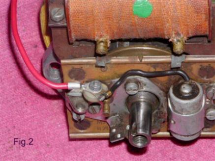
The connection is circled in white.3. Take a 5 ft. piece of red hook up wire, strip the insulation from one end, and attach a suitable lug. Connect this lug that you just installed on the wire to the point terminal, the same terminal that you just removed the coil wire from. (Fig. 2)
This shows it connected.4. Run the wire that you just attached to the point terminal, up through the grommet in the engine case, along the wiring harness, and into your headlight shell. Make sure that you have plenty of extra wire pulled through the headlight shell, you will need the length, and any excess can be tucked out of the way, this will be explained later. This wire, and all wires that you are going to run into, and out of the headlight shell, should be run right along your wiring harness, and through grommets. 5. Take a 5 ft. piece of black hook up wire, (this is the only place that you will use this color of wire) and splice this wire to the black wire that ran from the coil to the points. A conventional wire splice can do this, or you can attach a suitable lug to your hook up wire, and attach the two lugs together with a small nut and bolt. (Fig. 3)
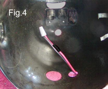
This shows them connected by a small bolt and nut. In either case, you must have a good electrical connection, and the splice needs to be well insulated. Run this wire, just as you did the previous wire, into the headlight shell, and leave plenty of extra length. 6. You should now have two new wires in your headlight shell, one red, one black. Clip these to a convenient length, ideally they should be long enough to extend out of the front of the shell a couple of inches. Strip this end of these wires, and wire nut them together. Mark the red wire with a piece of black tape. You could use black shrink tubing. (Fig. 4)
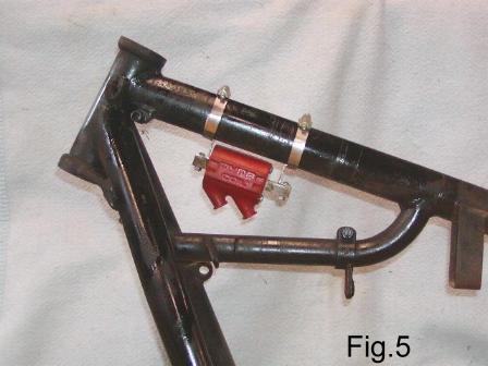
If you have done everything correctly, the bike will now be able to start and run on the magneto. Try it out. 7. You will now need to mount your new 6-volt coil. You want to place it between the top frame rails, so that the gas tank will hide it once it is reinstalled. (Fig. 5)
The mounted coil.The power circuit for your 6-volt coil.8. Locate the 15/54 terminal on the ignition switch. You can locate the 15/54 terminal inside the headlight shell as follows. Look straight into the headlight shell, at the top you will see the ignition switch. The 15/54 terminal, is the terminal farthest back on your right, the bikes left. Connect a piece of red hook-up wire to the 15/54 terminal, (Fig. 6)
The red wire on terminal 15/54.9. Run this wire along your wiring harness, and attach it to a primary terminal on your new coil, on a dual output coil, it doesn?t matter which side. Make sure you use a lug to make this connection. (Fig. 7)
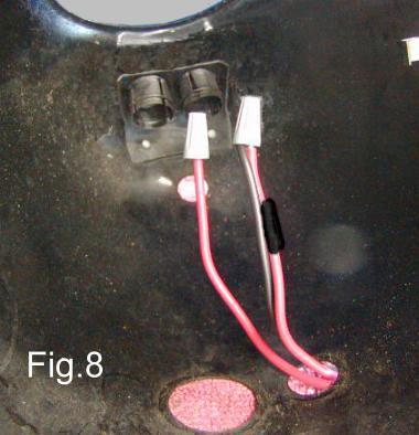
10. On the other primary terminal of the coil, attach another red wire, using a lug, and run that wire along your wiring harness and into the headlight shell. Just like the other wires that you ran into the headlight shell, you want this one to have about the same extra length inside the shell. Clip this wire to length, strip the end and put a wire nut on the stripped end to insulate it. If you have done everything correctly, you will now have three new wires inside your headlight shell that have wire nuts attached to them. There should be a red wire (with black tape) and a black wire, connected by a wire nut, and a separate single red wire with a wire nut on its end. (Fig. 8)
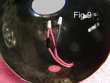
On the right are the red and black wire connected by a wire nut. On the left is the single red wire with a wire nut to insulate it. 11. Install two high-tension leads of suitable length with sparkplug connectors onto your new coil. 12. You can now reinstall the headlight, gas tank, and front engine cover. 13. Tuck your extra, (battery coil), high tension leads up between the tank and frame. In that location, they are out of sight but ready for immediate use. 14. You have now completed your battery backup ignition system. At this point you can, if you choose to, hide those extra wires that you ran along your wiring harness with electrical tape, or you can simply zip-tie those wires to your wiring harness. How to use your battery back up systemWhen your magneto coil dies, simply open up your headlight shell, and locate the wires that you have installed. Remove the wire nut from the paired red and black wires, and separate the wires. Remove the wire nut from the single red wire, and wire nut it to the formerly paired red wire. Now put the loose wire nut on the end of the black wire. (Fig. 9)
Replace your headlight, disconnect your magneto high-tension leads from your spark plugs. Tuck them up and out of the way. They now will have no spark. Connect your battery back up high-tension leads onto your spark plugs, and you are ready to ride away using your battery ignition system. When you return the wiring to normal, be sure to use the red wire with the black marker to attach to the black wire. The plain red one again hangs free. The Bosch points are small and will last almost forever with the magneto ignition system. Now they are operating with a battery coil system and the current is greater. They will wear much faster than normal. This is to get you home only. If you want to continue to use this system, I would suggest using the Pentacom points plate that employs standard Chevy points. They are cheap and can be found in any auto parts store. I do not recommend this points plate for the standard magneto ignition system. I want to thank Lonnie Walker for writing this and offering pictures of his bike, even though it is in parts. I suggest that you email him directly with your comments and questions. jwalker6@sc.rr.com He also has a wonderful article written about how to lace and tune a BMW wheel. More BMW info |
|
This page was last edited:
08/21/2006 - copyright
Duane Ausherman |