Repair, replace, and adjust the controls and cables for the /2, /5, and later.
This page is about the BMW motorcycle models R26, R27, R50, R60, R69, R50/2, R60/2, R50S, R69S, R50/US, R60/US, R69US, R50/5, R60/5, R75/5, R50/6, R60/6, R75/6, R90/6, R90S, R60/7, R75/7, R80/7, R100/7, R100S, R100RS.
So much of this information is identical between the /2 and /5 that it can’t be separated.
Introduction
This page has grown like cancer. It started very small and is over six times what I had anticipated. It is no longer my page but a compilation of many people’s ideas, tips, and photos. I try to give credit, but it is impossible now.
Castings and levers
The castings for both throttle and clutch are cast aluminum, sort of a high-quality “pot” metal. All were spray painted a gloss black. They fit only 22 mm diameter handlebars. 22 mm equals .866,” and the American 7/8″ equals .875.” Never try to slide them over an American 7/8″ sized bar. The casting usually breaks, and it is costly to replace. I measured eight 22 mm bars spanning 25 years and found a wide range. The older ones were .862″ to .866″ and the newer ones up to .868.” The only 7/8″ bar I have to measure is .878,” or a bit big.
Sometimes the casting resists going over a 22 mm bar. I use a flat-blade screwdriver as a wedge to slightly open up the “pinch” part of the casting. Don’t try this to fit it on a 7/8″ bar.
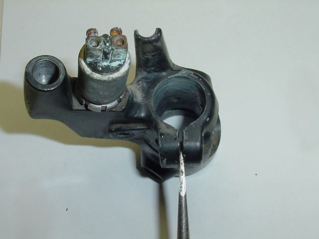 Photo #1
Don’t use any lubricant on the bar to install the casting. The bar and inside of the casting must be clean. Check the bar for nicks that may stop the casting from sliding on freely. Dress them with a file or stone. The throttle tube may get lubed later; more below. One of the most important items to check for on your control is the perch wedge. This part is what keeps the casting from rotating on the bar. The use of some nonstandard piece of metal may not “bite” into the bar. This will require that the pinch screw be tightened up more than desirable. I prefer to tighten it up so that it will rotate with a strong twist. I keep the casting tight enough that it doesn’t move with normal use. I reason that if the bike falls over, or worse, the casting will have a chance to rotate. That is much better than bending or breaking the lever.
Casting position
The casting position is important for comfort and safety. If the lever is too high, it is hard to pull it in the downward direction. It can make you sore from frequent use, such as riding in city traffic. It also takes too long to reach it, so safety is an issue. If the lever is too low, it is harder to pull. It is less distance for your fingers to travel in a panic, so the time will be shorter.
I will describe correctly adjusted castings. If you draw a line from your shoulder and through the handlebar, it should also go through the lever. Another way of saying it is that the levers must be pulled directly toward your shoulders. Pulling “down” or “up” is making your body work harder.
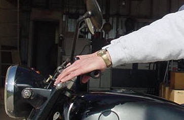 Photo #2
Your arm and extended fingers on the lever should look about like this in Photo #2. It should be a straight line from your shoulder to your elbow, wrist, and the lever.
Levers
Before WWII, BMW used Magura levers for almost everything. They were, and may still be, the highest quality lever on any machine. I have, on occasion, been able to straighten one that is bent almost double. It is easy to straighten one that got bent at only 90 degrees. Use the characteristic of “cold flow” that some alloys exhibit. Mark Huggett tells me that the levers are made of die-cast zinc.
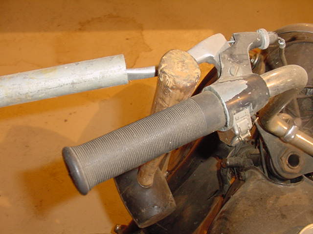 Photo #3
Photo #3 shows the pipe going over the lever and a hammer handle going in between the bent lever and the grip. Move it very slowly. It is safer on a warm lever, so heat it. It would take at least 15-30 minutes to fix a badly bent one. Sometimes I get bored, quit, and come back later to do more bending. I have only seen levers break when in a sharp kink or gets straightened too quickly. If the bike fell, the lever got bent almost instantly, not slowly. It seems that it can take one fast bend and maybe no more. If one breaks off, perhaps it has been straightened once already. A few times, I have straightened a lever more than once.
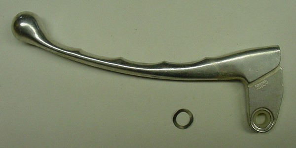
The lever ends can be filed down to get rid of minor road rash. Magura levers are mounted with a very thin wave washer to reduce vibration. The washer can go on the top or bottom of the lever. The wave washer part number was supplied by Roy Rowlett and is 32 72 1 230 071. It fits in between the control casting and the lever. A lever with the ball end, finger grooves, and washer can be seen here. The levers have changed slightly over the years. Before 1965 the levers were pointed at the end and had no finger grooves. In 1965 BMW introduced finger grooves and a ball end for safety. In 1978, I think, they changed the line to have a “dog leg” and no finger grooves for more comfort. The lever needs to be lubricated from time to time. A drop of oil from the dipstick is enough.
A variety of castings have been used over the years. Some have a hole for a mirror, and some are plain. The clutch side mirror hole is a left-hand thread. That way, the wind pressure tends to keep it tight. The throttle side has a right-hand thread.
Switches
Many types of high-beam switches have been used, one was typical for the USA, and the others were for the rest of the world. When the Earles fork models came out in late 1955, no turn signal provision was available. Some owners made up turn signals to suit. I don’t know the exact year that the now-famous bar-end turn signals were made available. I “think” it was around 1958-60. A new BMW would come with one of the two throttle castings shown below.
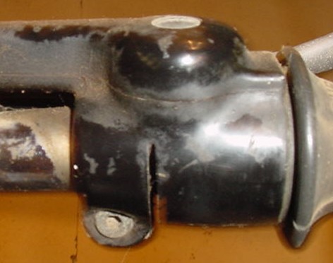 Photo #4
Photo #4 shows the no flat casting
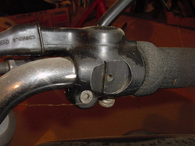 Photo #5
Photo #5 shows the typical flat on the casting
On the throttle side, a “flat” was machined for mounting the turn signal switch. The stock rubber grip came in two types. The older one had the rubber cast over the end for bikes without turn signals. One could cut a hole in it for the turn signals. BMW also made one with end holes. Later on, mid 60’s, BMW had only one with a hole cut in the end and a black plastic cap covering the hole.
Retrofitting turn signals onto older BMWs.
Here is what I think happened, but I don’t know for sure. BMW offered up a kit to retrofit the bar end turn signals onto the older bikes. A template was with the kit for drilling two holes in the throttle casting. That made a place to mount the “adapter” piece that would allow the mounting of the turn signal switch. A variety of switches were used, and I recall at least three different ones. Dave in Michigan provided these next four photos. Thanks.
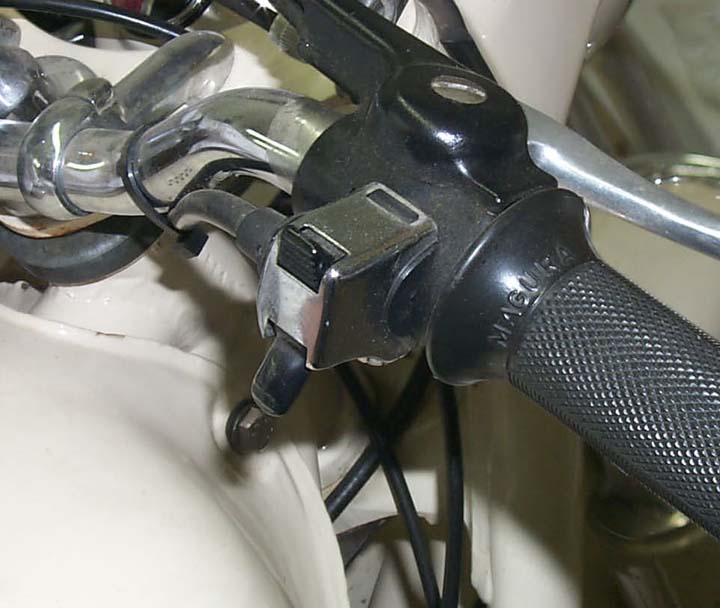 Photo #5
Photo #5 shows the finished product
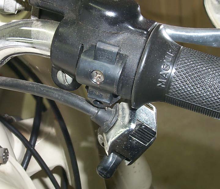 Photo #6
In Photo #6, the switch was removed to show the adapter mounted on the casting. The screw is not original, as no Phillips were used in the production of the early bikes.
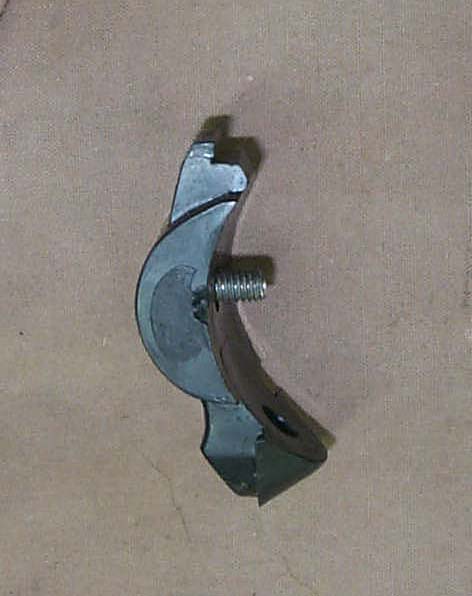 Photo #7
Photo #7 shows the adapter with the mounting screw. The switch mounts in two places. It “hooks” at the top, and a screw is used at the bottom, the same as the usual USA switch on the left side.
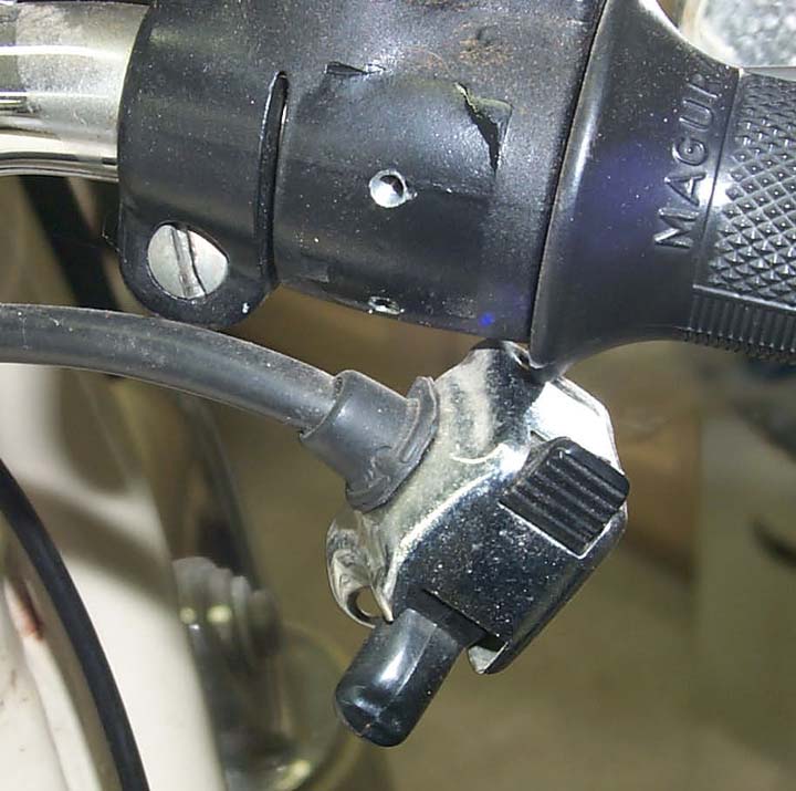 Photo #8
Photo #8 shows the two holes that were drilled into the casting for mounting the adapter. From a close examination of the casting, it appears to have some cast-in “dents” above the main hole to help locate the adapter. This suggests to me that Magura may have cast this just for this switch adapter. I do not recall ever seeing this. The ones I saw were done by the owner or mechanic, probably by using the template.
Generic switch
The number of motorcycle manufacturers in central Europe was quite large. Many used Bosch or Hella electrical accessories. A switch was provided that could be used for turn signals and fit directly on the handlebars. This made it hard to reach, and I saw very few of them.
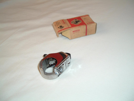 Photo #9
Photo #9 shows that the adapter is mounted on the usual switch. Photo from Ash, thanks.
Another type of switch
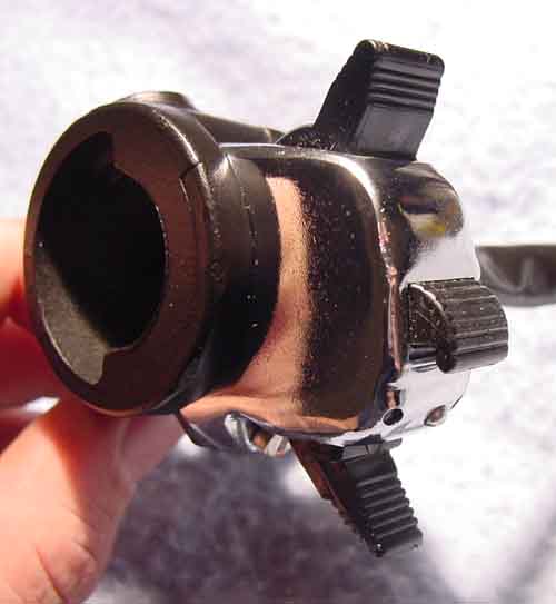 Photo #10
Picture donated by Dale Thomas, thanks
Photo #10 shows a switch that is a bit unusual, and I have only seen a few of them. It is mounted on the left side and serves as (top to bottom) a High/low selector, horn, and high beam flasher. The high beam flasher works even if the headlight is off, as in the daytime. Europeans used it to warn slower vehicles that one is approaching, so please move over to the right.
Front brake switch
Until about 1954, BMW didn’t even provide a switch for the rear brake. In 1968 or 69, the state of California required that the front brake switch the brake light. Blame the passing of that law on me; a long story. That way, either brake would show that the bike is stopping.
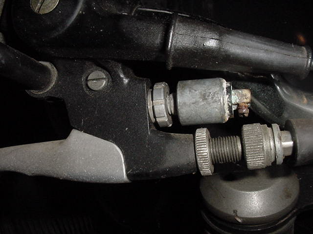 Photo #11
Photo #11 shows the switch on a /5, but it is the same for a 1969 US fork model. The 1968 telescopic fork model didn’t have a front brake switch. The switch has the rubber dust cover removed, and this one has no wiring hooked up. Notice the corrosion on the terminals.
Clutch switch
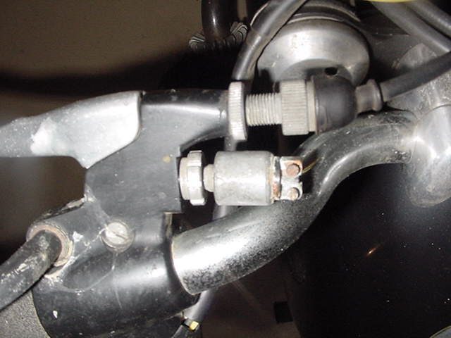 Photo #12
Photo #12 shows the same switch on the clutch side. It made the rider pull the clutch lever in or be in neutral before the starter would engage. The same brake switch was used on the clutch side in 1974 only. For 1975 they went to a smaller one; see below.
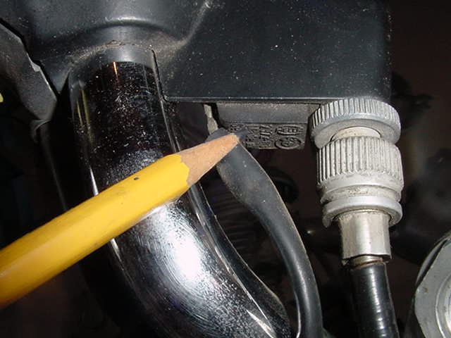 Photo #13
BMW used this switch from 1975 on.
Cables
The cables used by BMW are of high quality. A Brit. named Bowden developed the cable, so it is called a “Bowden cable” in the German parts books. It consists of an outer sheath or jacket, in black, made of some plastic. Next is a metal spiral that is the outside part of the “working part” of the cable. Being made as a spiral, it can flex easily. Next is the inner “wire,” which is the pulling part. The metal spiral must not be “compressible.” I understand that today’s clutch, front brake, and throttle cables have a Teflon liner between the wire and spiral to reduce friction. These Teflon cables must not be lubricated.
The storage and packaging of cables can affect their operation. You probably have seen some shops store cables by hanging them vertically on a rack. That is, by far, the best way to do it. I was disturbed to find more and more cables arriving in prepackaged shrink wrap with the cables all coiled up. The time spent in a coil will give them a “set.” That set is the spiral being pulled apart.
A quick test of a cable is to let it hang vertically. The inner part should almost drop from gravity. At most, it should only take a very gentle touch to lift it or push it down. This test takes some experience, so don’t throw a cable away based on this. Start “testing” every cable you come across to learn. A throttle cable that has significant resistance will cause tuning trouble. Replace them.
If you need cables of a special length, they can be custom ordered or built in your workshop. I have repaired and made up many cables. Flanders used to sell kits of quality cable ends for those wishing to make cables.
Throttle cables
The throttle cables are very reliable. I have seen them break from an accident. I saw one on a /2 last so long that where the little ferrule was fastened onto the cable at the carb end, in the slide, it wore down to the point that it pulled through and would no longer work. (see notes below) I have seen them seize/rust up from sitting out in the rain for a few years. I have never seen a /2 throttle cable break from old age.
We would first replace them because the outside metal spiral would get stretched and become a “spring.” That spring would compress and make synchronization impossible. One carb would get its slide lifted, and the other wouldn’t start until the spring got compressed. Even worse is that they might start lifting at the same time, and as the needed tension increased, one would begin compressing the spring while the other side was lifting. Mid-range would be “out,” but the start of the throttle pull would be correct. The result is vibration because one side is doing too much work at some part of the rpm range. An inspection of the cables will reveal the “stretch” example shown below. Always replace them as a pair.
The second reason is that they had too much resistance and would cause trouble with allowing the engine to go back to a consistent idle rpm. First, we would try some lube, and that often fixed the issue. The later Teflon-lined cables are not to be lubed.
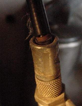 Photo #14
If you look very carefully at Photo #14, some of the black plastic jacket is failing to cover the spiral. At the top of the visible spiral, a tiny reflection of light can be seen between adjacent spiral coils. That reflection is off of the wire inside. We shouldn’t be able to see the wire. When the throttle is opened, the tension on the wire will cause the spiral to try to compress. It acts as a spring and will compress a bit. It is most likely that one side will compress more than the other. This throttle cable is bad, but I might not replace it yet. This small error occurred because the cable was slightly bent at the adjuster. You can see it. Over time, the spiral has taken on a set with one or two spirals spread apart slightly. I have seen a 1/2″ total spread and wire showing between each wrap. In that case, the carbs just can’t be brought into sync.
Routing
Cables would last the longest if they pulled straight, but they are always routed with one or more curves. The more gentle the curve, the less drag, and longer life, and it will have an easier lever pull. I would love to tell you how to route them, but that is not always possible. Due to variations in bars, tanks, and other accessories, one must figure it out for that specific bike. Keep all cables away from the coil connections on the /5 and later. The push-on connections can rub through the plastic jacket and short the ignition system. That happened on our race bike, and yes, it was in a race. We saw it on a few customers’ bikes too. After you find a successful path, tie and wrap them gently to the frame backbone so that they won’t move easily. As a final test, always move the handlebars from lock to lock to check for a change in the cables.
BMW uses a unique system for pulling on the throttle cable. It provides a straight pull at the control end. No other company of that era had a system nearly as good. It uses a bevel gear drive to pull on a small piece of chain. Other companies allowed the cable to wrap around the bar, and with each throttle opening, it flexed some. Eventually, it would break. This bevel gear system is more expensive, but with proper lubrication will last almost forever. It requires some adjustment that is a bit strange the first time an owner does it.
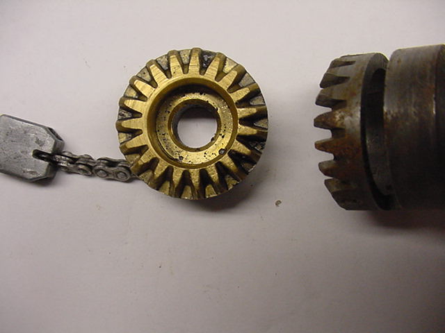 Photo #15
In photo #15, the brass gear has been turned over to show how it looks. Look very carefully at the lower teeth, and you can see some worn teeth. That one is still usable, but not great. The tube shows no such wear. This brass gear is for the /2. The /5 had a cast pot metal gear.
The brass bevel gear isn’t designed to provide a linear pull. It was done so that the first few degrees of twist only pulls a small amount. During the mid to upper range, it pulls much faster. This gives you precise control of rpm at the lower end. I mention this because this requires the bike to be adjusted in a certain way. It is easy but not obvious at first.
Basic throttle cable adjustment for the /2
The /2 and /5 have almost identical throttle assemblies. The /2 has no special markings on the gear teeth like the /5. In that aspect, the /5 is slightly easier. If your /5 has good cables and you want to apply this procedure, go ahead.
These directions assume that the cables are not stretched or made with too much wire sticking out. You can’t know that, so proceed and see what happens. You are not going to get into trouble. If one or both of the cables are “stretched,” then it will be impossible to synchronize them correctly.
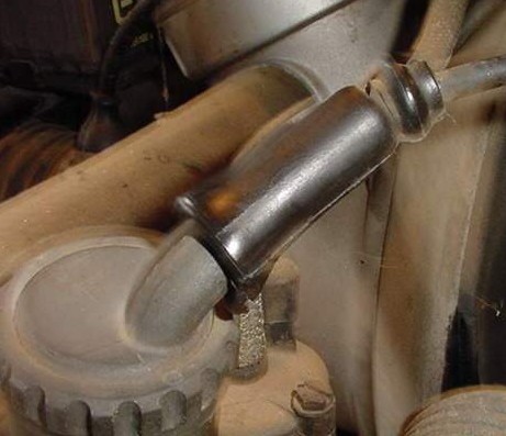 Photo #16
Rubber boot
Slide the rubber boot up and off of both carbs at the cable adjuster. Only the slide carbs have this rubber boot. The CV carbs don’t have it as they don’t need it. More on this later.
Both of the adjustments probably look like this.
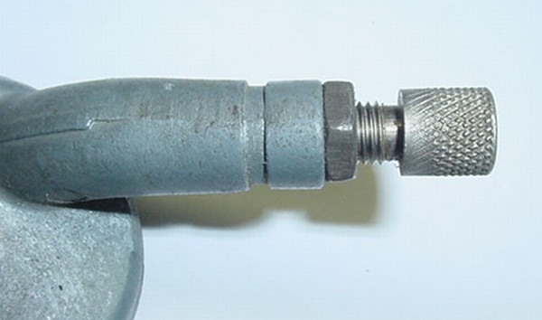 Photo #17
They should have the same amount of threads on each carb adjuster as in Photo #17. If not, then one cable “inner wire” is too long. You can tolerate some difference, but if you find one adjuster all of the way down and the other one almost out of threads, buy new cables.
 Photo #18
They should look as shown in photo #18. For a good starting point, adjust them till they do. Notice the gap between the knurled adjuster and the locking nut. I like to have one thread up from the bottom. It gives me some “play” room. More on this later. I would consider them ideal if they both look like this.
Note from Mark Huggett. The carb tops displayed above are original and require a right and left. Now BMW provides a universal top with a screw-in brass fitting that can be rotated to adapt to each side. The problem is that this brass arm is 10 mm longer than the original, and this takes away from the free play.
Magura throttle gear adjustment on the BMW motorcycle
Read this procedure over again and again until it makes sense. It takes me less than 2 minutes to perform, but that is after years of doing it several times every week.
At this point, the throttle cables should have some play. The play has been increased by the amount that you turned the adjusters down. We will now “fix” it at the top end. This involves a rather clumsy operation the first time, but it would seem easy if you were to do it several times in one day. You may have that chance, especially since this is your first time.
The /2 and /5 have marks to show the proper gear teeth matching. The reason that this is important is that the brass gear is a cam. It pulls on the cables slowly at first and at a higher rate as the throttle approaches 1/2 or more throttle. This is designed to allow the amount of opening to be carefully controlled by the rider at lower rpm. At slow speeds, the amount of power can be easily controlled. At higher settings, it will open faster.
While this is nice in theory, one has some amount of adjustment in the teeth to properly control the slack in the cables. It is more important to have the cable slack taken up fully by the bevel gears.
Feel the throttle “play” or looseness that is now evident. Remember this amount of play. Turn the throttle grip to the point where it would start pulling on the cables.
1. Remove the screw holding the throttle cap. The /5 and later have a rubber boot to keep dirt out. It must be slid back quite a ways to allow this next operation.
 Photo #19
At this time, you could use a shortcut and leave the screw in only one thread. Lift the cover on the right side, and it will look like photo #19.
 Photo #20
You could drop down to step #7 and proceed. However, I recommend going through the whole thing at least once. You will learn more and also ensure proper lubrication.
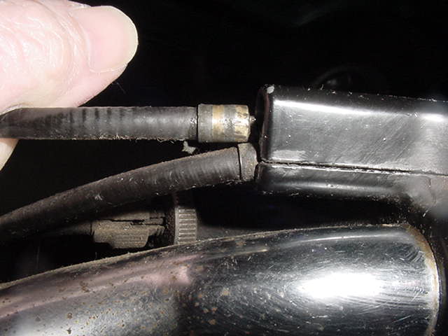 Photo #21
2. Pull the upper throttle cable, with your left hand, back (to the left) until you see the wire, like this. The lower cable is now “captured” and can’t jump out accidentally.
3. That is photo #22, but I can’t label it, sorry. Very carefully, lift and wiggle the cap up, being sure not to let anything move. Only lift it enough to free the cap from the throttle grip. Read #5 and #6 below. The throttle cable ends can come out easily, so be careful. It wouldn’t be a disaster, only a nuisance.
You may now relax the throttle cable in your left hand. The cap has a hole for the outside of the cable to hold it in place. The slot for the cable wire is so small that one can only get the wire through. That is why the cable must be pulled back. Understand this part, as it is important, and you will use it later.
4. Make sure that the bevel gear area is well-greased. Clean out old dry grease. Make sure that you grease the channel that the pull block runs in too. Use any thin grease. The grease will need to be checked yearly for contamination, water, and amount.
5. During normal operation, the throttle grip tube won’t come off of the handlebars.
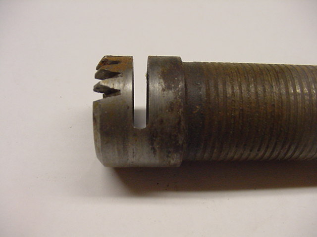 Photo #23
The tube has a slot in it, as shown in photo 23.
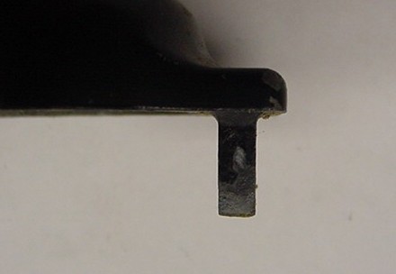 Photo #24
Photo #24 shows the cap tang.
6. The cap that you just removed has a “tang” that sticks down into that slot.
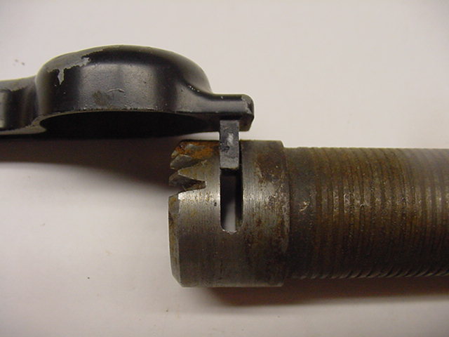 Photo #25
Photo #25 is what you would see if the casting were invisible. The cap holds the throttle grip tube from coming off.
7. The photo below is in error, as the cap should still be there to keep the cables in place. With the top lifted, the grip can be pulled slightly to the right.
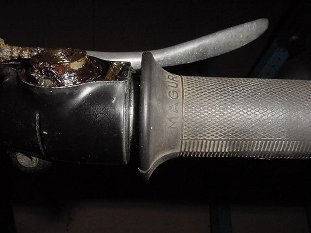 Photo #26
Photo #26 shows to only pull it out enough, about 1/8,” to unmesh the teeth of the bevel gear drive mechanism of the throttle. On the /2 throttle tube, shown below, there is a spiral spring inside the tube at the outer end.
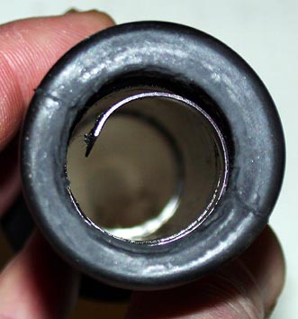 Photo #27
Photo #27 shows the /2 spiral spring by Bernd Kupper. Thanks
The purpose of the spring is to provide resistance from the grip, easily returning to idle. It is a crude “cruise control.” Its tension is only adjustable by the amount of grease or lack of grease between it and the bar. You don’t want to allow it to come off of the bar. If it does, it isn’t the end of the world, but now it must be started back on. That takes a turn in the wrong way to allow it to “walk” onto the bar. The /5 and later don’t have this feature. They have an adjustable throttle screw as a type of “cruise control.”
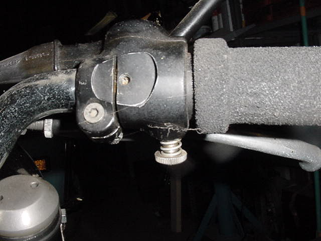 Photo #28
Photo #28 shows the screw with the spring around it, and underneath the control is the /5 and later “cruise control.”
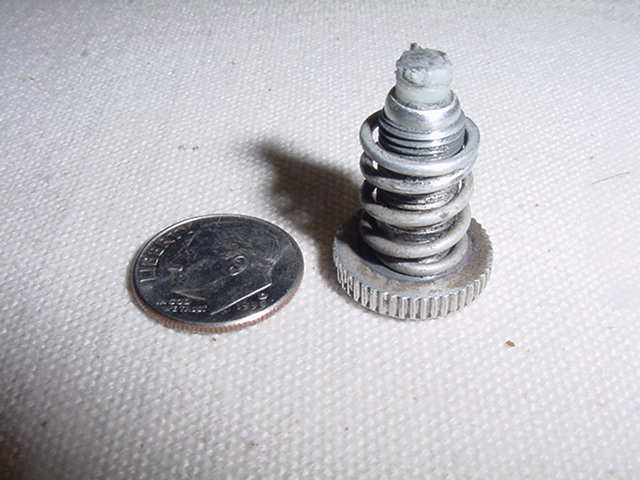 Photo #29
Photo #29 shows the look of the part. The spring is “captured” on the screw. The white plastic is what rubs against the throttle tube to provide the drag. This part can fall off, and we sold lots of them. If you wish to have no throttle cruise control, loosen it just enough that it no longer provides friction, and it won’t fall off.
8. Now that your left hand is holding the cap up and your right hand is holding the throttle tube grip, turn the grip in the direction of shutting down and going to idle. The amount is the amount of play you were told to remember at the start. Gently shove the grip back into the casting so that the teeth mesh again. Again, as in step 2, pull the top throttle cable back. Lower the cover while gently wiggling it so that it sets down into the slot in the throttle tube. Relax the top cable to fit into the cap’s hole. You don’t need the screw yet. Hold the cover down and test the throttle grip for play. It should be very little. If it is still too much, repeat the steps, starting at #2, and try to catch the next tooth. The amount of play that one tooth will take up is about 1/8″ at the grip. You can’t usually get all of the play out, only most of it. The lower adjustment can easily take up any residual play. Replace the screw. Leave the throttle fully in the idle position.
9. The cables will now be out of synchronization. Basic sync is very easy. Grab one cable at the carb and gently pull on it. You should be able to feel the play. Rotate the adjuster to where about one thread of play remains. You must leave some play. Adjust the other cable.
10. Start the engine and let it warm up a bit. This next step takes two people. You will ask your helper to gently turn the grip just barely off of idle. The amount of turns is very little. You go to the rear of the bike and lean over and put your head up to the rear fender. Make sure that your head is centered on the fender. This only works if you can hear with both ears. As the throttle comes off of idle, one side may pick up first. The stereo effect will make it obvious. Go to the other carb (the one that didn’t respond or did so later) and turn the adjuster out (counterclockwise) a bit. Test again and adjust as necessary to get both sides to pick up at the same time.
This is a less accurate alternate method but doesn’t require an extra person. With the bike warm and idling, bring the adjuster up until it just starts to pick up the slide (increase the rpm), stop, and adjust it back down one turn to give some slack. Do the other side exactly the same way and amount of slack. This will get you extremely close and good enough for most of us.
Now that you are happy with the sync, here is a very important test. Turn the handlebars from side to side and watch for any change in the idle speed. You might need more “slack” or “free play” in the cables to prevent the bars from affecting the speed. You might need to reroute the cables to fix it.
11. You have the basic sync done, which may be enough for you. Don’t use the wrench to tighten the locking nut. It is not only unnecessary, but I have seen the threads pulled out of the carb top. Use only your fingers to tighten it. First, do your best with your fingers on the nut while holding the adjuster. Then, grab both the adjuster and nut and tighten both. Yes, you will slightly alter the sync, but it will be the same amount on both sides. Do the other side too. If you need to adjust it again after a few days or miles, you don’t need a wrench, just your fingers. The sync won’t “creep” as you ride.
12. If your bike is one with the boot on the cable, as on all /2 and later slide carbs, it is time to move it down again. The purpose of the boot is to try to seal off air and water. Notice how very tight it is? As you push it down, also rotate it for ease in getting over the carb top. Once it is in place, you are not finished. You must rotate it to let it extend again. As it got pushed down, it gets fatter and shorter. When you release it, the thing wants to grip the cable and lift it up. This will mess up your sync. I have never noticed a mixture change from the boot being “up” or “down.” My fear of air leaking into the carb via the cable is long gone. I use another modification. I cut the lower restriction off of the boot. This is about 1/8″ of the boot This allows it to move up and down without grabbing the carb top. The rain is kept out, as before, but now the boot has no chance to mess up the carb sync. It is now easy to slide the boot up, adjust the cable and slide the boot down again, all with no tools.
13. You may have a vibration at road speed that you suspect may be the sync. It is possible that it is caused by one carb slide being pulled higher than the other. It is possible for the slides to lift off in perfect sync and then be out of sync at some road speed. Here is one way to deal with it. Loosen the cable adjuster lock nut on the left side. Warm up the bike and take it up to the speed that you suspect may be out of sync. With your right hand holding a steady speed, reach down with your left and slightly turn the cable adjuster one way and then the other way. Judge by an increase or decrease in vibration. The vibration in the mirror may be a great indicator. You could leave it at the place where the vibration is the least. You will probably find that the idle won’t lift off equally as you previously adjusted at step # 10. You must decide which is more important to you, slightly less vibration at road speed or smoother “pick up” off of idle. It has been mentioned that riding with one hand may put you at risk for a wobble. That is true, but the bike has a really big problem if it is that unstable.
14. If #10 and #13 give drastically different results, go through them again. If that is the best that it gets, then go to my page on tuning to read more about other factors.
15. Another method has been used by shops and some owners with some success. It was used in my shop with little success. My best mechanic, Bryan Hilton, didn’t like it. The idea is that if each cylinder runs, by itself, at the same rpm, above full advance, the two will put out equal horsepower.
The accessory electronic ignition systems for the /5 and later are working out well for owners. It has been suggested that those systems don’t like to have a spark plug shorted out.
16. The R75/5 throttle cables must come straight up for some distance from the carb. If it immediately bends over towards the underside of the tank, it can affect the sync. I have seen owners tie-wrap the cable to the spark plug wire to keep it vertical.
Spare cable storage
The serious rider carries spare cables. The best way is to mount the spare alongside the cable in use. This means that it can be quickly and easily replaced. The tank need not be removed. Cable ties need not be cut and replaced. One need not dig through luggage to find it. Protect the ends from dirt and water.
It might look a bit funny, but the savings in time and trouble offset the ugly look.
Front brake and clutch cables
The front brake and clutch cables on the /2 and /5 do break. They usually break at the top end, and it is usually due to a lack of maintenance. The lower ends of both are a straight pull and not subject to bending, like at the top or at the control lever. The break is within about the first 1/2″ (5-15 mm) of the barrel. The barrel begins to stick in the lever due to a lack of oil. To inspect it is very easy. Slowly pull the lever and watch the wire that is now exposed. It should move freely and not in small jerks. The jerks show that the barrel is sticking in the lever. The wire bends slightly to accommodate the stuck barrel. That bending is what finally causes it to break. One drop of oil is enough to fix it. Depending on the weather and amount of riding in the rain will determine how often to do it.
Removing a /2 cable at the top end.
This one is so easy, but somehow it seems to be largely unknown. This works for either the clutch or brake cable. I will use the clutch as an example in the photos. Loosen the lock nut, run the adjuster all of the way in, and line up the cut-out parts with the slot in the casting.
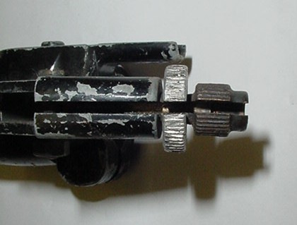 Photo #30
Photo #30 shows the section that was cut out to make room for the cable. All three slots are lined up. Notice that the adjuster is adjusted all the way in.
Pull the lever all the way back. Grab the outer sheath of the cable in your right hand and pull. Slowly release the lever, and your right hand will pull the outer sheath away from the adjuster. It will look like this.
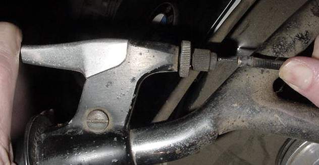 Photo #31
Photo #31 shows the cable pulled out of the adjuster
Now the cable can be taken out through the three lined-up slots. It will look like this
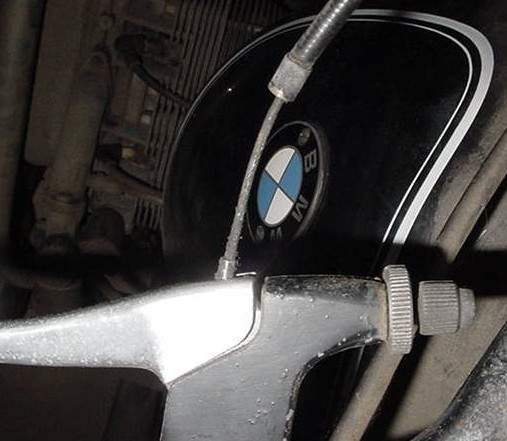 Photo #32
Remove the cable by dropping it downwards and out of the barrel pivot hole. To install it again is sort of a reverse procedure. Hook the outer sheath on the adjuster locking nut and pull the lever. It will look like this in photo #33 below.
 Photo #33
Slowly release the clutch lever while pulling with your right hand. The cable sheath will follow it, as before, giving you the slack necessary to rotate the wire back through the slot and in place. Release the cable and adjust the adjuster as needed. This adjustment should only be about a turn or two out. Any extra slack should be adjusted at the bottom end. This way, you have the room to easily change (tighten up) the adjustment as the cable stretches out.
Removing and installing the /5 and later clutch cable
The /5 uses a slightly different system from the /2, and it takes a bit more work. The advantage of the /5 system is that the upper cable end is completely covered and stays clean and dry. The /2 can collect dirt, and that causes wear. I much prefer the /2 system as it is easier to adjust, lube, change, and inspect.
The /5 (and later) clutch cable must first be removed at the lower end.
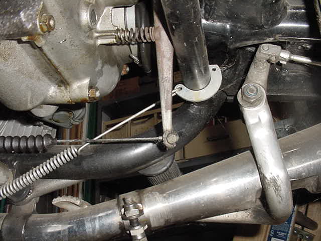 Photo #34
Photo #34 is looking up at the clutch arm and cable. This is the place where it must first be removed. It can be done in two ways; fast or slow.
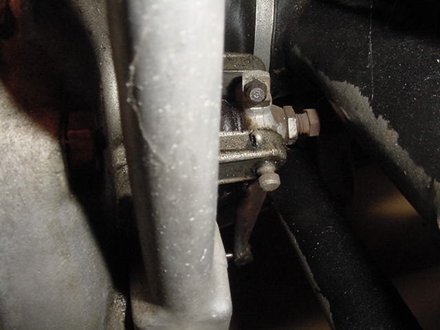 Photo #35
Photo #35 shows the slow way. This is looking at the adjustment bolt and locking nut for the gross clutch cable adjustment. See the 13 mm locking nut? Loosen that and then back off a turn or two on the 10 mm adjuster. The faster way is below.
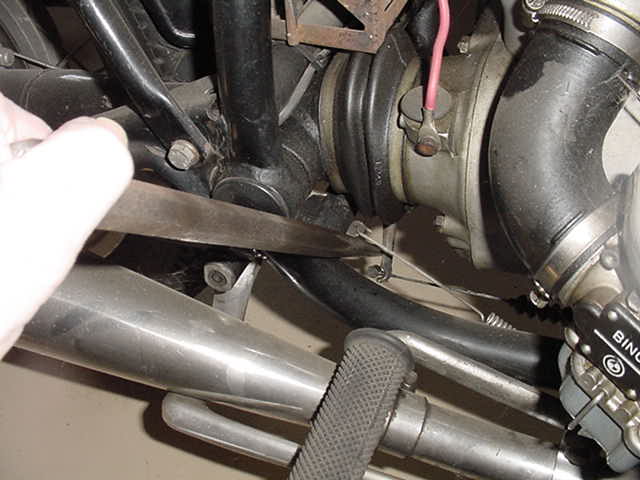 Photo #36
Photo #36 shows where I stuck a lever behind the clutch arm and levered it forward. It is the white thing going in from the right side of the bike. This will easily give enough slack to reach in with your right hand and drop the cable off of the arm.
Now the clutch cable is loose at the lower end. At the lower end, shove the wire fully in towards the sheath, which is towards the upper end. This will give enough slack at the hand clutch lever to pull the barrel retainer out.
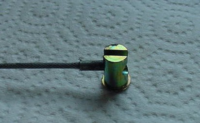 Photo #37
Photo #37 shows the upper end of the clutch cable with the retainer in place. You can’t see this on the bike because it is all inside of the clutch casting and lever. This is only to show you what you are trying to remove. The round thing is the barrel retainer. The slot that you see is too narrow to allow the retainer to be pulled out. That is why you are getting all of this slack described above.
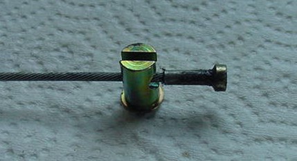 Photo #38
Photo #38 shows how it looks with enough slack. The wire will allow the barrel retainer to be pulled down and out. Now the clutch cable is loose at both ends.
Do you want to replace it? I can’t give you the full procedure because each combination of tanks, bars, and accessories makes it custom. You will need to thread it down and along the right side of the frame. It is a bit tricky at the back end.
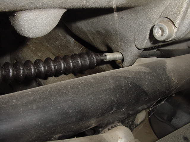 Photo #39
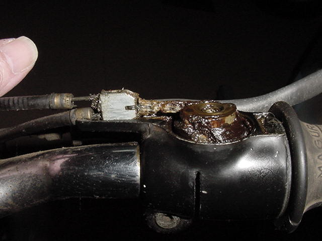
In photo #39, you can see what the installed cable looks like at the transmission housing. This is the part that holds the sheath from moving and is called the “boss.” Some difficulty may be encountered when trying to thread the wire with the accordion boot around the boss. The cable end and boot can be run down and in between the transmission and the frame. Then move it back and under the boss. Then you will be able to finish installing it. It is the reverse procedure. Be careful not to allow the barrel retainer to drop out and get lost on the floor. The new cable will need to be adjusted with the lock nut and adjuster. Run the 10 mm, bolt adjuster in a few turns with your fingers. Stop when it starts to get tight. Try the clutch hand lever for the feel of slack. Adjust as necessary and tighten the lock nut.
 Photo #40
Photo #40 shows you about how much “slack” or “free play” should be at the clutch lever.
BMW motorcycle clutch adjustment for the pre-1981 clutch
There is nothing hard about adjusting the clutch cable. It is really simple and can be done in a variety of ways. The end result must still be the same. One must end up with a bit of free play at the top end, at the lever. See the photo above.
First off, let’s understand that both the top adjustment (hand lever) and the lower adjustment at the transmission do the same thing as far as the adjustment goes. The lower one is “gross,” and the upper one is “fine.” One turn on the bottom is about equal to 6 turns on the top.
Because BMW used a couple of variations in clutch parts, they ended up with a few different traits. This simple method takes them into account.
 Photo #41
1. One “should” have the upper adjustment “out” about 2-3 turns, as shown in photo #41. This allows one to easily “run it in” a couple of threads to free up the adjustment for a really hot run when the clutch heats up a bit. This does not happen to all BMW clutches or all hard riding. It does happen to some, and I allow for it. I suggest that you do too. This way, you have an adjustment in both directions at your fingertips.
2. Once the upper adjustment has been set, then finish with the lower one. Run it in by hand until you feel some resistance, and then lock it down with the nut. You may need to hold the bolt with a wrench while tightening the lock nut.
3. The adjustment should be in the ballpark, so check it. One should find “that bit” of free play. Where and how you measure it is not important, but some free play must be there. If you measure the ball end tip of the hand lever, then it is about 1/4″ to 3/8″ or a cm or so. Too much would be 1/2″ to 3/4″, and 1/8″ would be too little. Too little, and one runs the risk of it tightening up due to heat and not fully engaging and then slipping. Too much free play, and one runs the risk of not fully disengaging. That will make shifting difficult.
You may need to go back and make a small adjustment to get it right. See the previous two photos above.
A properly operating BMW motorcycle clutch will not start to engage until the hand lever is out past 1/2 way. The length of travel where it starts to engage and finishes. is minimal and about 3/4 of the way out. THAT IS NORMAL.
 Photo #42
In photo #42, you see the adjustment at the top of the adjustable barrel that is almost all of the way out. It is past time to fix it. It very well could have the proper free play and work perfectly, but one has lost the ability to make a fast adjustment while sitting at a stoplight. This applies to both the clutch and front brake.
Improving the very “hard to pull” /6 BMW motorcycle clutch lever.
This mod will work on just about any BMW. I did the same thing on my VW-powered BMW in 1967. In 1974, with the advent of the /6, BMW’s clutch pull was excessive. Vech at Bench Mark Works has a good solution.
Riding with no clutch cable
If the clutch cable breaks while riding, it is usually due to a lack of maintenance and inspection. When it happens, you have the chance of that retainer falling out and getting lost on the road. If you carry a spare clutch cable, I suggest that you also carry a spare retainer.
If the clutch cable breaks when on the road and you have no spare, don’t despair. You almost have to be riding solo when this happens, but I have had a few customers who managed with a passenger. I have ridden motorcycles several times with no clutch. The BMW lends itself to this easily as it has high torque at low rpm.
Get the engine running and warmed up. Allow it to idle in neutral, push the bike as fast as you can (I do this while astride), and put it into first. Or, you can be a cowboy and run alongside the bike and jump on as you reach maximum velocity. It will be at about the right rpm for that speed and gets you going in first. Take it up to only about 1200-1400 rpm and preload the shift lever. Let off on the throttle and increase foot pressure on the shift lever. It will pop into neutral if you are gentle. Now, as the rpm has dropped to around 1000 or so, shift it into 2nd gear. Going into 3rd is about the same, but there is no defined neutral, and it may sort of jerk as it hits 3rd. That is why you must use low rpm. Stay in the lowest gear that will work for your road speed. Downshifting takes a bit more technique to do it smoothly. You need to try to find the false neutral and increase the rpm a bit before shifting it into the lower gear. I strongly suggest that you learn this technique before you need it. It will give you confidence that you can travel without the clutch. It may also convince you of the need for clutch cable maintenance and to carry a spare.
I have seen serious long-distance riders sort of semi-install the spare clutch cable. It is a good place to store it.
Protecting the clutch cable
On the /2 and /5, the clutch arm has a round spring that keeps tension to hold the arm rearwards. That spring provides the tension to keep the cable hooked on the arm. If the free play is too great, the spring can fall off, and then the cable can drop off of the arm. You are now without a clutch. Keep your clutch cable free play correctly adjusted. Sometimes we used a short piece of thin wire to attach the spring in place. If it falls off, then at least you still have it and can put it back right again.
The /2 and /5 have a cotter pin to hold the clutch arm pivot pin in place. This system worked out well. On the /6, BMW changed it, and problems occurred. The pin is held in place by a clip. The clip is made of soft stamped sheet metal. It had a way of not getting seated properly and falling off. The pivot pin could then slowly work its way out and fall off. The clutch arm then fell off too. Sometimes the three-piece throw-out bearing would fall out too. More typical was for the pivot pin to work its way out of one side. Then the next time the rider pulls the clutch lever, the pin is put in a large bind. The single casting boss that is still holding the pin breaks off. Sometimes both sides will break off. All of these pieces are required to have an operating clutch. This clip was changed to a normal C clip, but it still needed to be set properly. Check by trying to push and pull the pivot pin out with your fingers. It should stay exactly in one place.
Other cables
The speedometer and tachometer cables require occasional lubrication. I like to lube them well and let them drip overnight to drain. With both ends loose, one can turn an end by hand, and it should be free and without any “catches” in it. One symptom of a cable with a catch is an unstable needle. These cables shouldn’t be allowed to have any sharp bends in them. The lower end of the speedometer cable plugs into the transmission at the right rear. It must be covered with a boot in good condition. This cable is famous for directing the water into the transmission and rusting the bearings. If you find the oil level too high at the fill hole and grayish, think of foamy oil in the transmission, which is an emulsion caused by water. Check the speedometer cable boot. Replace with clean oil, ride it several hundred miles, and replace it again.
Installing the speedo cable must be done carefully. At the upper end, very carefully insert the square end into the speedo. Before fastening the collar, take a very close look at the place where the outer flange butts up against the speedo housing. There should be no space there. The flared-out part of the speedo cable should be flush with the speedo housing. Otherwise, you run the risk of putting pressure on the speedo internals and ruining your speedo.
When installing a new or rebuilt speedo unit, always replace the cable too. I have “cheated” a few times when the cable is still excellent, with no permanent bends in it, and gotten away with it.
Choke cables on the R75/5 are of two types. These cables have no Teflon liner and need lubrication. The actual “choke” is really a fuel enrichener. It changed only slightly during the run of the /5 models.
The timing retard cable on the R68/R69 needs lubrication. I have no idea if they are now provided with the improved Teflon liners yet. The magneto with the timing retard lever has some other issues.
Perch wedge
The perch wedge is the common name of an essential part of the clutch and throttle controls. It was used on all BMW motorcycles from 1956 till at least the /7 and maybe longer. Its function is to keep the clutch and throttle castings from twisting on the handlebars. Turning the throttle and having the whole throttle casting turn is inconvenient. The part is still available. I do know that Vech has it. It seems expensive, but it always was costly. If you suffer the consequence of failing to have it, that price will seem very cheap indeed. Install one on each side. Don’t waste your time trying to find an alternative to the original part.
The perch wedge is almost invisible when in place. One end of it can be seen if one looks from the center of the bike outwards and under the casting. In the gap, where the two parts of the casting almost come together to tighten, is a small triangular space. In that space is the wedge. It is common for grease and dirt to cover it up. I then use a thin wire to stick in the greasy hole. If the wire goes in, then it has no wedge.
Many owners aren’t even aware of its existence. The owner typically removes the throttle or clutch casting, and the wedge falls onto the floor. IF it is found later, the owner has no clue what it is or from where it came. Check your bike to see if you have them.
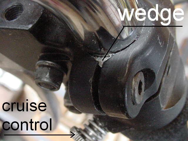 Photo #43
If you look closely at photo #43, you can even see the teeth of the wedge.
 Photo #44
Photo #44 shows the wedge seated in place in a casting.
The screw that tightens the casting squeezes the two parts together and forces the perch wedge into the chrome of the handlebar. The slightly curved part is made up of several lines, or serrations, that “bite” into the bar. This keeps the control casting from rotating on the handlebar.
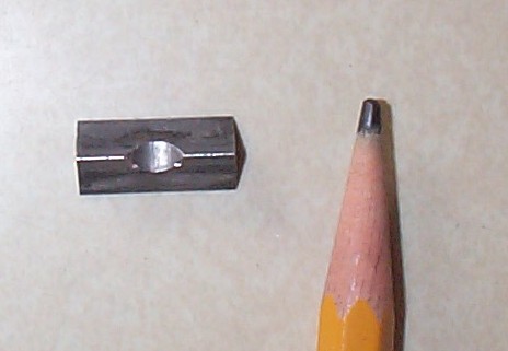 Photo #45
Photo #45 shows the top view of the groove that the tightening screw “fits into.” This keeps the wedge from moving sideways.
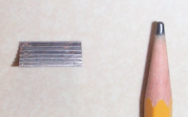 Photo #46
Photo #46 shows the serrated edges or teeth that “bite” into the bar.
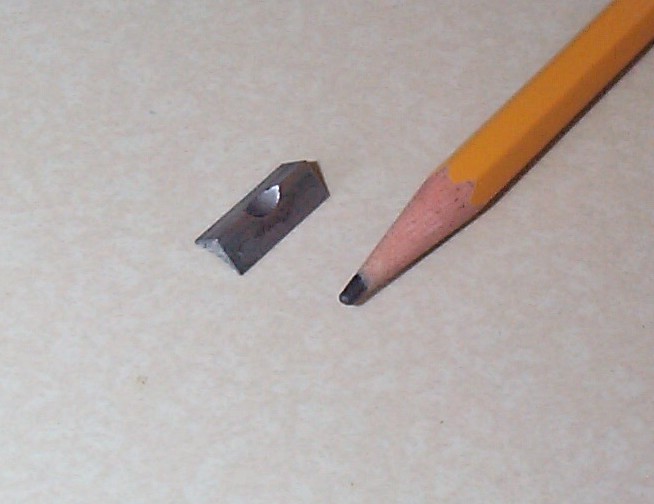 Photo #47
Photo #47 shows a vertical view of the end of a BMW motorcycle perch wedge.
Grip installation
The original grips were Magura. However, this advice applies to all grips.
Grips may be cut off with a blade or scissors. Clean the bar very well.
The most popular way to install it is with hairspray as the lubricant and glue.
Coat both parts with rubbing alcohol and slide it on.
If you have compressed air, it is easy to remove and install grips. Just direct the nozzle under the grip and blast away. Clean the handlebar and install the grip the same way with air pressure. YouTube video
Updated 30 March 2023