|
BMW motorcycle rear brake repair and adjustment |
|
The purpose of the rear brake is to stop the rear wheel, not to stop the motorcycle. The tire stops the motorcycle and that efficiency depends upon the specific tire. If you can't easily stop the rear wheel with moderate foot pressure, then it needs some attention. This page is only a start and will be expanded when time allows. Removing the rear wheel from your BMW motorcycleThis procedure may vary a lot, depending upon year and accessories mounted. A tire that is wider than specified by BMW may make the job harder too.
Inspection of the rear brakesGrab the foot brake lever and wiggle it sideways. It should only have a slight movement. Yours wiggles a lot because of wear caused by a lack of maintenance/lubrication. Remove the brake lever for inspection, cleaning and lubrication. First, back off the rear brake adjustment at the final drive. Run the wing nut back several turns.
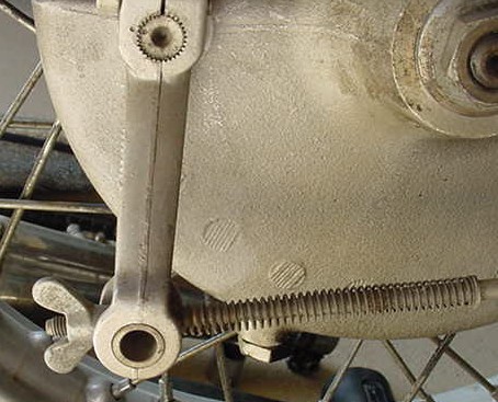
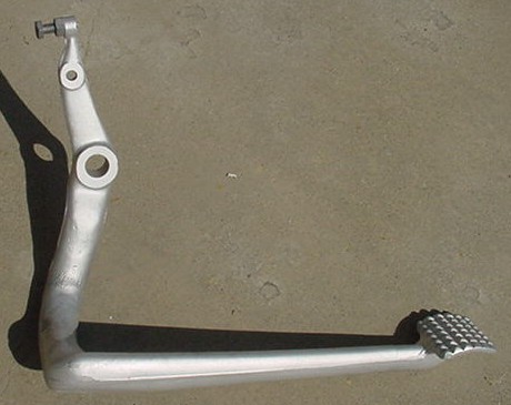
The normal adjustment should look something like this. This is about average. See the threads showing? That is about average. See the slightly less than 90 degree angle between the brake arm (vertical part) and the rod (horizontal part) with the spring? When the brake is applied, that angle comes closer to 90 %, which is where one gets the maximum force applied to the brake, depending upon the cam wear. See the upper shaft and the two punch marks at about 10 O'clock? I made those punch marks. This allows one to remove and reassemble it in the same position. The arm is mounted on the shaft on splines. There is little variation allowed. You should punch the marks before you remove the arm if you think that the arm is in about the correct spot. This allows you to reinstall the arm in the correct position the first time. This shaft is something that should be removed for cleaning and lubrication. More later on this.
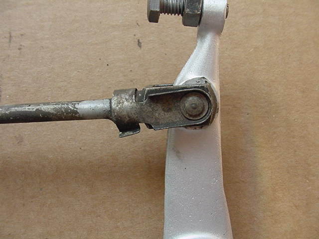
This is what is back behind the driveshaft and is hard to see.
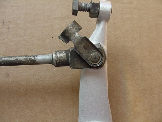
Lift the fastener to this position. It now comes towards you. It will probably be impossible to get out. They get rusted up and so I suggest some WD 40, or your favorite anti-seize oil. You may even have to punch it out from the other side with something long and slender.
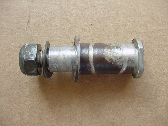
This is the bolt that is now ready to be removed. On the right are two flats for a wrench. Hold the bolt by the flats and remove the nut shown on the left. It is kind of tricky at first to reach both, but it can be done. Examine this bolt. See the hole for grease? See the rust that is to the right of it?
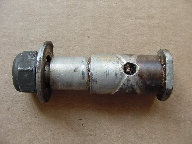
This is the backside. I have cleaned out the grooves for the grease so that they show up well. They kind of "spiral" around the bolt. They are not rusted because they had grease in them. The body of the bolt is rusty because it didn't get greased. As soon as the grease is forced out, the water gets in. The rust now "grinds" away at the tube welded on the frame. The rust makes friction and some braking action is lost here. The frame tube gets larger and the brake lever is now sloppy. You can't easily fix the part that is now worn, but you can make sure that it doesn't wear more. The photo above shows the washers in the proper position.
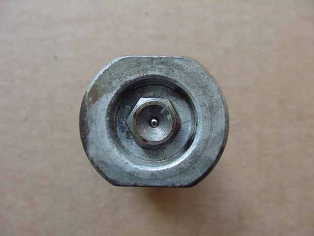
This shows the head of the bolt with its grease zerk in the middle. Remove it with a 7 mm socket. Take care not to lose it, as I have no idea where one gets another one.
The old grease can be very hard to get out. I often start with a drill bit and turn it by hand. The flutes allow some of the hard grease a place to go and get pulled out.
Solvent and an old fashioned Q tip will clean the hole out.
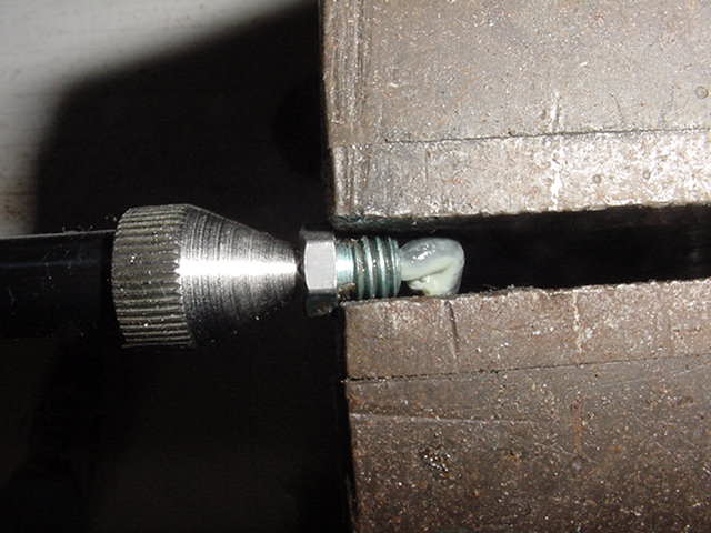
Don't freak out, the zerk is held in the vise by the grease gun, not the jaws. This is to test the zerk. You can see some grease that just got pumped through.
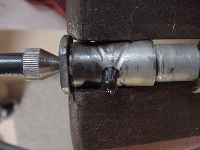
Here the zerk has been reinstalled and tested. See the grease that was pumped through? Don't assume that it will work unless you have tested it.
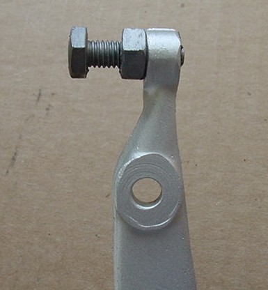
This is what the lever should look like.
This shows the adjuster bolt in about the usual position.
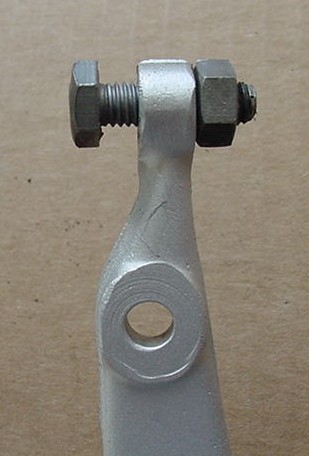
You might need to move the nut around to the other side to get the adjustment. That is an unlikely option and I would be concerned if this is needed. If one is doing something special, then maybe it is OK. On an average bike this would only be needed if something is bent or altered. I would want to find out why. With the adjuster bolt screwed in this much the foot brake lever would be raised up a lot. It isn't unknown for the brake lever to get bent. It usually occurs between the empty hole and the adjuster. They even break off. The part can be welded back on again. The bolt/nut shown serves two purposes, to operate the brake light switch and be a stop for the lever position. By adjusting this bolt, one can move the lever up and down. Your preferred foot and toe position may be improved by this adjustment. Don't be afraid to play with it a bit. Many of these bikes have never had the lever in the best position for the rider. You may also move the foot pegs up or down too. Any adjustment with these parts will require some adjustment of the wing nut at the final drive. I will be adding more text and pictures to show the rear brake shoes, final drive, wheel and splines. See my other page related to this topic.
|
|
This page was last edited:
09/05/2006 - copyright
Duane Ausherman |