BMW motorcycle headlight/ignition switch and keys for the /2
This page is about the BMW motorcycle models R26, R27, R50, R60, R69, R50/2, R60/2, R50S, R69S, R50/US, R60/US, and R69US, with some /5 information. Some of this info applies to earlier models also. These headlight and ignition switches have been used since the late ’30s and up until the end of the /5. Here are the things that go wrong.
Your black plastic nail key may be made incorrectly.
1. The chrome cover plate gets scratched up from riders who use the key in one hand to slide the black plastic forwards to make a space to insert the key. Use both hands.
2. The round brass place has the hole for the key and also has a slot for turning the headlight on and off. It gets “wallowed out” from riders “pounding” the key into place with the palm of the hand. Never “hit” the key into place.
3. The black plastic rain cover breaks off earlier than necessary. This is because riders use the tip of the key to push it forward. One should use two hands to insert the key. Pull the black plastic forwards with one hand while the other gently inserts the key. Insert it and gently wiggle it down and into place.
4. The key goes in with some effort because it lacks lubrication. Inside are two ball bearings that are held in place with a small spring that wraps around and holds the balls in place. The balls drop into the grooves in the key to hold it down. If the balls and spring lack oil, then it is hard to get the key in place. One must press on it, and that causes the keyway to get wallowed out. A drop of oil, once a year, is enough.
5. Headlight shells get badly scratched by the use of the flat metal (emergency) key. Riders often keep it on a keychain, and the “extra” keys flop around and chip the paint. Use the flat key all by itself.
6. The key can’t be pushed down far enough to maintain the contact. One feels the need for a longer key or a large rubber band to hold it down. Over time one of two things can happen. The whole switch assembly can become slightly loose, or the contact points in front can become misaligned.
How to use the black plastic key
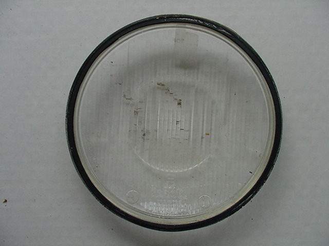
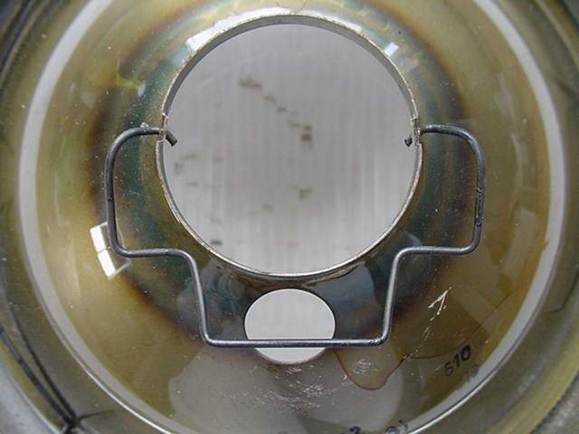
When the key has been left in the “half in-half out” position, it is tempting to bang it into place. That will cause the keyway that turns the headlight switch to wallow out the narrow slot.
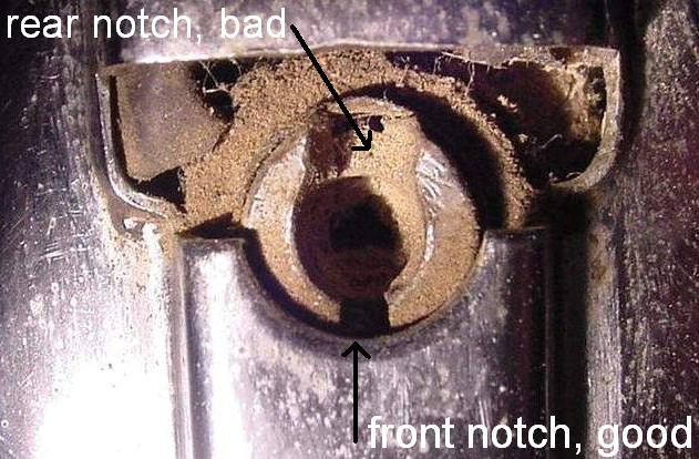
The bottom of the photo is the front of the shell. The above photo of an old headlight shell shows the round hole into which the ignition key plugs. The black plastic slider is broken and gone. See the notch for the keyway at the upper part? It is twice as wide as the one below the hole. That is because the key has been “hammered” in and “wallowed out” the keyway. The upper notch, or rear one, was once identical to the front or lower one. With this extra slop, the key may no longer turn the internal parts far enough to make contact.
If this happens to your switch, you can turn the key backward as a temporary measure. For a permanent fix, one must remove and rotate the round part so that the key will now engage the “virgin” slot that has been facing the front.
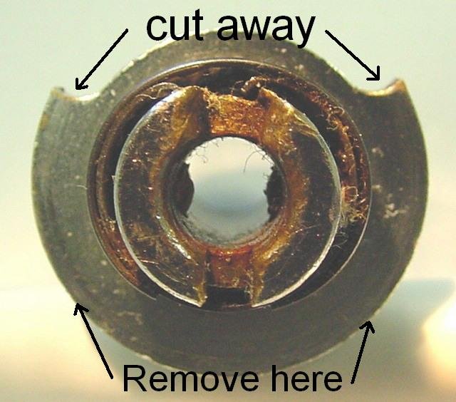
Photo by Jeff Kuzmanoff. Thanks
See the cutaway arc (about 10 O’clock to 2 O’clock) where the sheet metal has been removed? The “outer part” with the missing arc is virtually the limit for rotating the key for the headlight and parking light switch portion of the assembly. That must be done on the bottom side too. To do this requires removing the entire switch plate, removing and modifying the part shown, and reinstalling it 180 degrees from where it was. This isn’t a nice job as the switch plate is held in with 4 bend-over tabs of metal. With age, these tabs become brittle. These tabs will only tolerate a few bendings and then break off. I use a short screwdriver to bend the tab. The chrome cover also is held on with bend-over tabs. The ultimate life of the whole assembly is determined by the tabs, which means the owner must use care. It has been reported that one can soften the tabs by heating them to about red and then allowing them to cool slowly. I have never tried it, but it sounds correct. That process is called annealing. It could safely be done with one of those tiny propane torches.
You may need to replace the black plastic slider that keeps rain out of the round hole and headlight. All work can be done while the headlight is on the bike. It may help to remove the speedometer to get enough room to work. The switch plate must be lowered, and the chrome cover lifted. The 4 tabs should only be bent the least amount needed to loosen the chrome cover enough to get the broken parts out and install the new ones. I have heard of mechanics being able to thread a wire around the post and grab the spring. This would avoid the bending of the tabs. This would be great, but I have never done it.
The BMW headlight switch plate
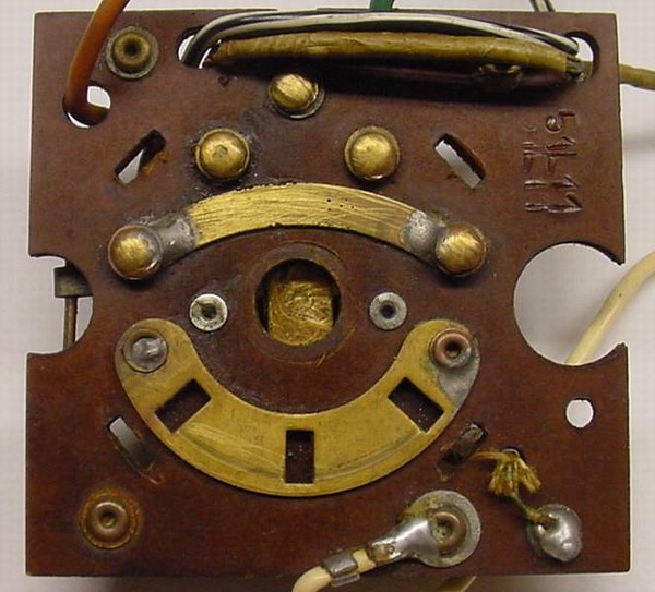
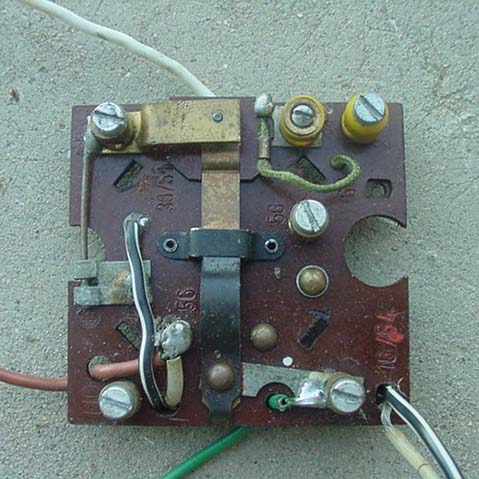
This is the headlight and ignition switch plate. Look for the 4 slotted holes that are all at a 45-degree angle and midway between the center and the corners. The slots are for the 4 bend-over tabs. The curved lower brass part has three rectangular holes (detents) for the light switch. Several terminal posts hold wires on the other side of the plate. The screws that hold them do come loose. Once a year, check them for tightness with a small slotted screwdriver.
![]()
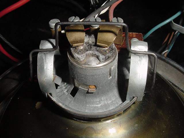
Here is the switch plate, as you would see it in the headlight shell. In between the yellow terminals are the two horizontal brass plates. They are the contacts for the ignition. The upper one is all the way up. This is how it looks with the key out, which is ignition OFF.
![]()
Now you can see the contact as it would look with the key down, which is ignition ON. It has a little tit, not seen here due to poor lighting, that contacts the lower arm. On the /2, it need not contact the lower one to allow the engine to start. Once it has moved down a tiny bit, it has broken the contact that grounds the magneto. The red/green lights wouldn’t be on, but it will start and run. If it fails to stop when the key is out, then it is most likely that the entire switch plate is slightly loose.
On the /5, the two must make contact to get power to the ignition system. It will only start when you see several lights lit up. In this case, you can see that the lower contact isn’t quite level. It is bent up just a tiny bit. That was probably done so that the two would make contact. It may need to be done when one finds that the key must be held down to keep the lights on. Bend this very gently and only a bit at a time until it is just right. The other reason that it might be bent upwards is that the whole plate could be loose and, therefore, lower than normal. If that is the case, bend the tabs up a bit more to hold it better. I would first try bending only the forward two and only the amount needed to hold it mounted firmly. If required, I would bend all four of them.
Are you having trouble keeping the key operating correctly?
Warning! Do not bend the actual spring, only the arm or the tabs.
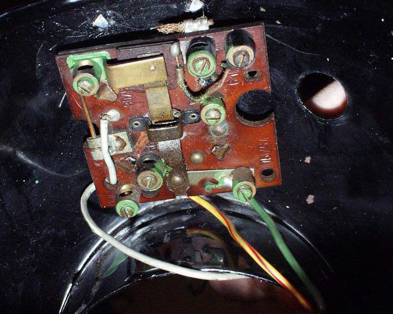
Here is the plate mounted in a /5 shell, but this part is almost the same for a /2. As time passed, 55-73, the switch plate became slightly more complicated, with a couple more terminals.
The various keys
Late 30’s to 56 black plastic “normal” key for the /3 series.
Late 30’s to 56 flat key, don’t use this on a key ring.
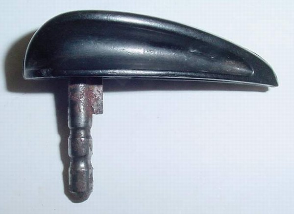
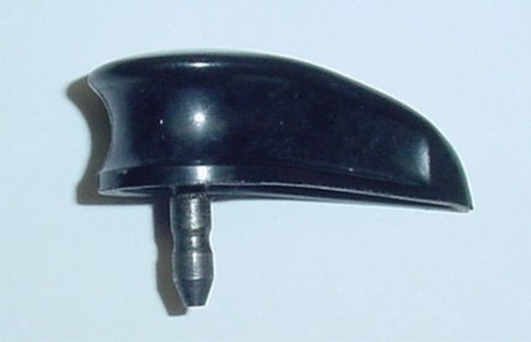
This is the black plastic “normal” key. The first model to use this key was the R25/3. It was standard on all of the Earles fork models late 55-69 and the /5 series 1970-73. Some of the keys offered today are not made correctly. Some are too short and don’t operate the switch properly. Some have the groove for the ball detent in the wrong place. Make sure that your key is correctly made.
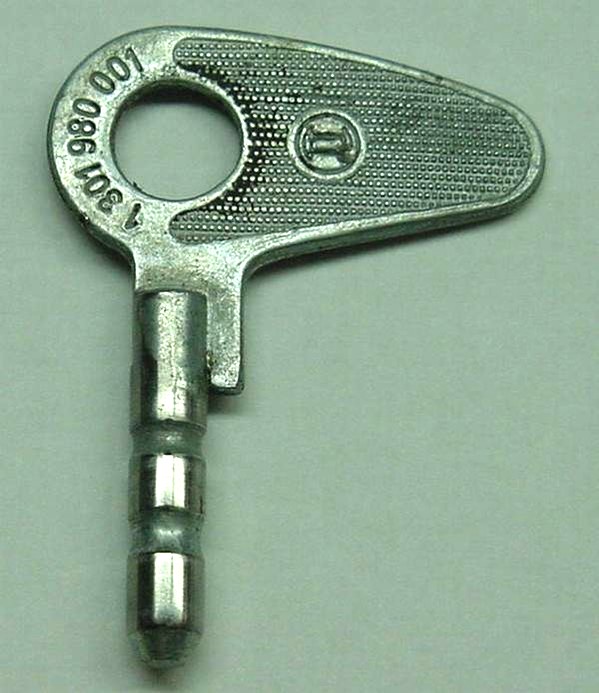
55 through 73 flat key, not for use on a key ring.
BMW motorcycle theft
Do these keys all look alike? There is only one key, and it fits all BMWs. The 55-69 type will work in the older bikes, but they stick up too far. All a thief needs to do to steal a /2 is to remove the ground from the magneto. Cutting the whole harness just above the engine can accomplish this in seconds. The /5 and /6 can be started by adding a jumper, a simple wire with alligator clips. It only takes a few seconds. The fork lock can be defeated in a few minutes. Your bike is easy to steal, so aren’t you glad that BMWs aren’t “cool” and fast? Be happy for that “stodgy image.”
The black plastic rain cover (slider)
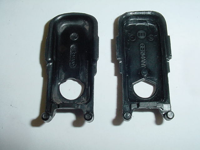
The black plastic rain cover breaks and is unavailable. A reproduction is available, but it is slightly different, and you can see the very small differences. These were sent to me by Lonnie to photograph for your information. Thanks so much. I do appreciate all that Lonnie and others have done to improve this site.
The weight is slightly different; the new one is 2.95 grams, and the old one is 4.4 grams. Both have a diameter of the pins that hold the spring to within .001″, but the new one has better quality control over its roundness. The old one is not shiny any longer. The new one is very shiny. I hope that the photos show several small differences in the molds, of which none are important. The main difference that I notice is the new one is far more flexible. It has been noticed that when installed, it can be pulled out forwards and then lifted up about 1/2″. In the right picture, the old one shows considerable wear on the place where the plastic rubs the key shank. The new one shows a “V” shape and is rounded on the old one. In normal use, the repo is great.
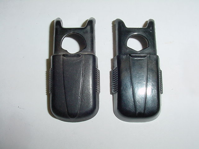

The old black plastic covers are shown on the left and the new ones on the right. The new ones are far more flexible than the original ones. This should reduce the tendency for the ends to break off.
Trivia time

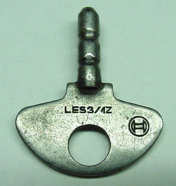
This is the key to open the toolbox on the top of many gas tanks from the early ’30s to the mid-’70s. It has a square end, but the properly sized slot screwdriver works just great. Many riders seldom used the key to open and close the lid. Just push down on the cover to compress the thick rubber gasket and hand screw the round fastener in only finger tight. Let go of the pressure, and the “lock” is quite tight. To unlock it, compress it again and turn it out with your fingers.
BMW motorcycle headlight rim, lens, and reflector assembly
BMW /2 headlight assembly
I hope that you will find answers to your questions about the assembly of the headlight parts. The parts underwent some slight cosmetic changes over the production years of 56 thru 69 but were all interchangeable. A turn signal indicator light was added to the US models.

This is the reflector, and that tab is located at the very bottom to help orientation.
This is a typical lens with the rubber gasket mounted. The stock gasket has “ribs” on the outside, and the smooth side goes against the glass. In the absence of a proper rubber gasket, black plastic, or cloth electrical tape. Probably any “thick” tape would work.
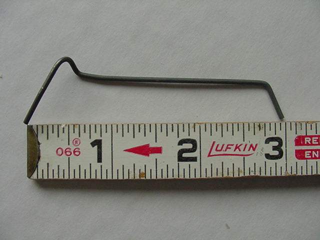
This spring is one of 5 used on the /2, /5, and /6 series. They were used from the late ’30s through the late ’70s or later. The left end has the “hook” on it to be started first in assembly. These springs can be reshaped as needed, and this one is perfect.
This shows how your finger must be used in mounting the spring.
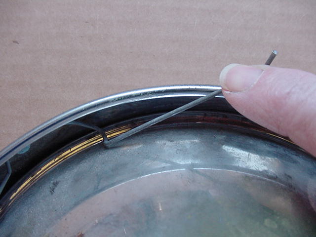
The hook is started under the rolled edge of the chrome headlight rim, and the index finger on your right hand pushes the right end down and under the rim edge. The spring was designed for a right-handed person.

The spring was “installed” properly. Next, another spring is installed nearly opposite to hold the lens/reflector centered while you install the remaining 3 springs. Often, one or more springs have been lost, and the assembly can get along with 4, but 3 is too few. Do not allow the springs to overlap each other, as it makes removal harder.

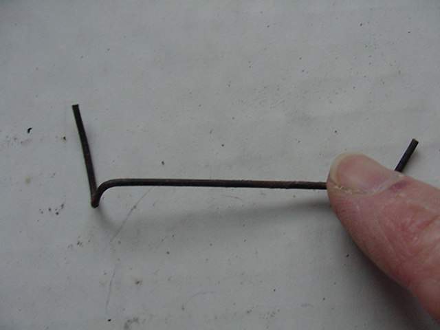
The bulb retainer spring holds the bulb holder (socket) onto the reflector.
Here it is installed on the reflector. Carefully install this spring. It is easy to bend it while trying to get the two ends hooked into the reflector holes. Before the bulb and socket are set into the reflector, the spring must be flipped upwards to allow the “park” light bulb to fit into the small lower hole.
The spring and bulb holder are in place.

This shows the positive mounting of the rim to the headlight shell on the /2 only. The washer is made of rubber, and its purpose is to retain the bolt so that it doesn’t fall out and get lost. If the shell and rim are perfectly round, then the retainer bolt will go in by finger pressure. The headlight assembly would stay in well by itself, and the bolt is only for insurance. If either is distorted in the slightest, the rim can jump off easily, and the bolt prevents that. This bolt doesn’t need to be tightened up much. This one is an example of over-tightening. It has bent the locating tab under the bolt downwards just a bit. The tab should be horizontal.
I am lazy, so I have included the later model-related information here. I will link it to this page.
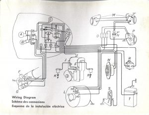
Electrical diagram for 1955-1960 /2
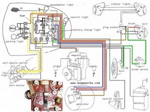
R51/3 electrical diagram above
The early /2 is almost the same. Original author unknown, sent to me by Mark Millard, thanks.
Updated 15 July 2022