This article is about the /5 and later models that used spoke alloy rims. The rims were all made of aluminum alloy by Weinmann.
The front rim is 1.85 X 19 and used a 3.25 X 19 tire.
The rear rim is 2.15 X 18 and used a 4.00 X 18 tire.
The first two years, 1970-71, BMW had serious failures of the spoke heads. You may read about the fix here.
Modern rim information by Mike Cecchini
Buchanan’s can supply just about any un-drilled rim on the market………even Borrani that are now back in production.
Personally, I’d much rather have Buchanan supply all the parts and drill everything to their spec’s so I know it’s been done correctly and have recourse should something go amiss……..which has never happened in the 20+ yrs I’ve been dealing with them. Send them your hub and they will supply everything and spoke up the wheel. You will get a finished wheel ready for the tire.
Also note that modern valanced rims, especially Excel rims (alloy or steel) are so much stronger than most so they can be tensioned to much higher levels for longer use and stay in tune. For instance, the max most rims can handle is 65-inch lbs of tension. Stock /2 front is done to 35-inch lbs and rear is done to 50-inch lbs. Excel rims can be done up to 100-inch lbs. Buchanan did mine @ 55-inch lbs as they’ve found this is best for /2 size rim (2.15″ x 18″).
Yes, Excels are a little more $100 –$150 vs $70–$80 ……..but you get a world class quality product that will run true for decades so your bike will ride smooth and straight.
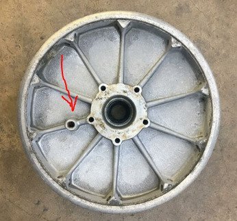
“My riding buddies and I noticed that hole 39 years ago and figured it was where a pin goes to align and hold the hub when turning the iron brake liner.”
————————————————————————————-
Richard Evans also provided a more detailed explanation of Bill’s comment.
Updated September 9, 2019
<!– /* Font Definitions */ @font-face {font-family:”Cambria Math”; panose-1:2 4 5 3 5 4 6 3 2 4; mso-font-charset:0; mso-generic-font-family:roman; mso-font-pitch:variable; mso-font-signature:-536869121 1107305727 33554432 0 415 0;} @font-face {font-family:Calibri; panose-1:2 15 5 2 2 2 4 3 2 4; mso-font-charset:0; mso-generic-font-family:swiss; mso-font-pitch:variable; mso-font-signature:-469750017 -1073732485 9 0 511 0;} @font-face {font-family:”Arial Rounded MT Bold”; panose-1:2 15 7 4 3 5 4 3 2 4; mso-font-charset:0; mso-generic-font-family:swiss; mso-font-pitch:variable; mso-font-signature:3 0 0 0 1 0;} @font-face {font-family:”Noto Serif”; panose-1:0 0 0 0 0 0 0 0 0 0; mso-font-alt:Cambria; mso-font-charset:0; mso-generic-font-family:roman; mso-font-format:other; mso-font-pitch:auto; mso-font-signature:0 0 0 0 0 0;} /* Style Definitions */ p.MsoNormal, li.MsoNormal, div.MsoNormal {mso-style-unhide:no; mso-style-qformat:yes; mso-style-parent:””; margin-top:0in; margin-right:0in; margin-bottom:8.0pt; margin-left:0in; line-height:107%; mso-pagination:widow-orphan; font-size:18.0pt; mso-bidi-font-size:11.0pt; font-family:”Arial Rounded MT Bold”,sans-serif; mso-fareast-font-family:Calibri; mso-fareast-theme-font:minor-latin; mso-bidi-font-family:”Times New Roman”; mso-bidi-theme-font:minor-bidi;} .MsoChpDefault {mso-style-type:export-only; mso-default-props:yes; font-size:18.0pt; mso-ansi-font-size:18.0pt; font-family:”Arial Rounded MT Bold”,sans-serif; mso-ascii-font-family:”Arial Rounded MT Bold”; mso-fareast-font-family:Calibri; mso-fareast-theme-font:minor-latin; mso-hansi-font-family:”Arial Rounded MT Bold”; mso-bidi-font-family:”Times New Roman”; mso-bidi-theme-font:minor-bidi;} .MsoPapDefault {mso-style-type:export-only; margin-bottom:8.0pt; line-height:107%;} @page WordSection1 {size:8.5in 11.0in; margin:1.0in 1.0in 1.0in 1.0in; mso-header-margin:.5in; mso-footer-margin:.5in; mso-paper-source:0;} div.WordSection1 {page:WordSection1;} –>
I have been thinking about that hole for some time. My background: manufacturing engineering
(not product design, but design for production-big difference)
A casting will include lots of special shapes:
‘positives’ (bosses) to allow for bearing housing,
‘negatives’ (holes for material saving, or machine time reduction)
‘sprues” (for molten metal entry)
and sometimes there will be surfaces (positives and negatives) for material ‘clamping’
and tooling considerations
(example: ears for milling table attachment)
but that hole
I have shown that same question to others in manufacturing,
and here is one guess:
that hole would be the perfect place to ‘drive’ the casting while the other side is being turned,
(the first cut in the raw casting would probably be the bore for the bearings)
With that center established,
a mandrel could be inserted and the all the subsequent machining
(drum turn, spline drive rivet holes, spoke holes) would require something to serve as an ‘index’
that hole could have been the ‘mate’ for the driving dog
—If you had to ‘jaw’ the casting to ‘finish turn’ the brake drum, then you would have
tooling marks on the outer peripheral surface of the hub… ugly