/2 BMW motorcycle ignition timing advance curve, measure, graph
1969 BMW Magneto Ignition Advance Unit Analysis
By Klaus Wolter, 11/23/01
I removed the mechanical advance unit from my 1969 R60US BMW motorcycle, with about 30K miles on it, and built a device to measure its timing curve. Below is a graph of my results. The upper line is the curve we got as RPM decreased, while the lower line is the curve that was generated as the RPM was increased. The difference between the two lines is probably the result of stiction in the advance mechanism.
The graphed data is the result of two runs, up and back down, with the RPM being measured every 2.5 degrees at the camshaft or 5 degrees at the crankshaft. NOTE: Since the advance unit is attached to the camshaft, both the measured rotational rate and degrees of advance must be doubled when we talk about these values relative to the crankshaft.)
The manual, which came with the motorcycle, has the following to say about timing: Ignition timing is 9 degrees BTDC (governor weights in neutral position). The range of adjustment is 30 degrees at the crankshaft. Max advance is 39 degrees ∓2 degrees BTDC. Since static timing is set for 9 degrees, we need to add the change in degrees, shown in the chart above, to 9 degrees in order to find how many degrees BTDC the ignition system is fired by this particular advance unit. If we want to find the maximum advance provided by this unit, we need to add 35 degrees to 9 degrees and come up with 44 degrees of maximum advance! This is out of spec. by 3 degrees since the maximum allowed advance is 39 degrees ∓2 degrees = 41 degrees. As a result, the data my son and I collected should not be considered sacred.
As I think about the results of our testing, I am struck by how crude the advance mechanism is. The stiction results in sloppy timing, as can be seen from the graph. Secondly, things like stiction are amplified by a factor of two because the mechanism is mounted to the camshaft, not the crankshaft. If my advance mechanism is any indication of the advance units built for the R60s, then I feel it’s a pretty imprecise system. On the other hand, my advance unit could be bad, or it may simply not matter. Either way, my test fixture showed me how the advance unit works, and it makes spotting a flaky advance unit pretty simple. The hysteresis between increasing and decreasing RPM was obvious from the start, even without a tachometer.
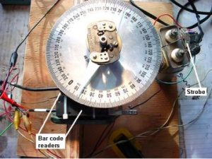
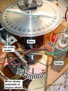
Device for measuring advance:
The device I built to make these measurements was kept as simple as possible without sacrificing accuracy. I used what I had, and it wound up not costing me a cent. Your mileage may vary.
The basic concept was to spin the advance unit up to 4,000 RPM while it was mounted to a wheel marked off in degrees. The wheel I happened to have was marked off for a full 360 degrees. I decided that a frequency counter would be a good, quick way to measure RPM. I had one that would measure from 1 to 500 MHz. I thought it would be easier to have the counter readout in RPM, so, using CAD, I drew up an encoder wheel with 60 black and white bars around the circumference. This encoder wheel was then attached to the bottom of the degree wheel. I happened to have several non-contact barcode readers, so I used one to read the black and white lines on the bottom of my degree wheel. The output was run to the frequency counter, and I was reading RPM! I turned a little arbor to hold the advance unit and the degree wheel.
The whole thing was then mounted to an old electric sewing machine motor that I had attached to a simple plywood stand. I drew a long line on the bottom of the degree wheel and added a second barcode reader. The output from this reader was connected to a crude but effective triggerable strobe light I had built years ago from stuff in my junk box. Once I got it working, the strobe would always flash at the same place as the degree wheel spun. It’s a lot easier to synchronize the strobe to the wheel than trying to read the wheel with an asynchronous strobe! (Yes, I tried it!)
I then cut out a simple double-ended pointer to keep things balanced and glued it to the advance unit, just below the camshaft, to work as my indicator.
Below are two shots of my setup:
Data:
My 12-year-old son, Keane, recorded the data as I manipulated a variac that controlled the speed of the electric motor. Below is the data that we entered into a spreadsheet and manipulated. This data generated the graph shown above.
| Degrees | RPM #1 | RPM #2 | Difference | Average RPM | Engine RPM | Degrees @ engine |
| 0 | 900 | 860 | 40 | 880 | 1760 | 0 |
| 2.5 | 950 | 1020 | -70 | 985 | 1970 | 5 |
| 5 | 1000 | 1000 | 0 | 1000 | 2000 | 10 |
| 7.5 | 1150 | 1200 | -50 | 1175 | 2350 | 15 |
| 10 | 1450 | 1430 | 20 | 1440 | 2880 | 20 |
| 12.5 | 2000 | 2060 | -60 | 2030 | 4060 | 25 |
| 15 | 2700 | 2680 | 20 | 2690 | 5380 | 30 |
| 17.5 | 2900 | 2880 | 20 | 2890 | 5780 | 35 |
| 15 | 2000 | 1960 | 40 | 1980 | 3960 | 30 |
| 12.5 | 1450 | 1410 | 40 | 1430 | 2860 | 25 |
| 10 | 1010 | 1010 | 0 | 1010 | 2020 | 20 |
| 7.5 | 850 | 880 | -30 | 865 | 1730 | 15 |
| 5 | 800 | 800 | 0 | 800 | 1600 | 10 |
| 2.5 | 620 | 600 | 20 | 610 | 1220 | 5 |
| 0 | 440 | 400 | 40 | 420 | 840 | 0 |
Key:
Degrees – How many degrees the pointer moved from 0 on the test fixture.
RPM #1 – RPM of the test fixture. This was our first pass.
RPM #2 – RPM of the test fixture. This was our second pass.
Difference – Difference in RPM from first to the second pass. (RPM #1 – RPM #2)
Average – Average RPM from the two passes.
Engine RPM – The average RPM X 2 for crankshaft RPM.
Degrees @ engine – Degrees at cam X 2 for degrees relative to the crankshaft.
Thanks
My thanks to Klaus for taking his time and expertise to assist the greater /2 community. He has also done far more than just this one project. They are a family that I greatly respect.
I enjoyed a visit with the family in late 2015 while traveling around the USA.
Updated 15 July 2022