electric starter troubleshooting hints
This page is about the BMW motorcycle models R50/5, R60/5, R75/5, R50/6, R60/6, R75/6, R90/6, R90S, R60/7, R75/7, R80/7, R100/7, R100S, R100RS.
There are four main components of the starter system. Each can be tested easily.
1. Battery.
2. Starter switch,
3. Starter relay
4. Starter motor.
I listed them in the likelihood of failure. I suggest testing them in a different order. This information assumes that you still have the original wiring and that nobody has altered it.
1. Most of the starter problems are related to defective batteries and/or connections at the battery. Will your battery operate both the headlights and horn? Do the lights go out when you push the starter button? When you push the key in, do the instrument lights come on but go out if the starter button is pushed? Those are typical indications of a weak battery or a poor connection. Try removing the wires to both terminals, greasing them, and reconnecting them.
2. To check the starter switch (button), remove the headlight rim assembly. Find the 4-circuit terminal block. It is a 6-terminal block starting in 72-73.

Photo by Brian Trotter. Thanks.
This is the 72-73 6 terminal block type. The colors aren’t in the same order as mentioned below. It matters little as you must only find the Brown/Black, and they are the third one from the bottom.
The block is at the end of the wires from the starter button. It is the place where the starter/turn signal loom wires are attached to other things. On one end will be the Blue/Black wire for the right turn signal. Next is the Blue/Red wire for the left turn signal. Next, the Brown/Black wire for the starter. Lastly is a Green/Red wire for the front brake light switch.
The starter switch only grounds the circuit. You are going to “duplicate” the switch. Push the key in for power. If you have no terminal block, then find the Brown/Black wire from the wiring loom from the right-hand control of the bars. Run a jumper wire from any good ground point and stick the other end into the terminal connector for the Brown/Black starter wire. Just poke it into the place where you see the set screw for a slot screwdriver.
If the starter turns, then that is proof that the starter is “good” but isn’t getting grounded. It is probably the switch that is failing to ground the circuit, but it could be that the wire going out to the switch is broken somewhere. The switch is the most likely place for it to be broken. The switches can be repaired. Instructions are elsewhere on my site (starter and turn signal switch repair) and on other excellent websites.
3. Test #1 didn’t make the starter motor turn? I suggest that one check the starter motor next. Remove the tank to gain access to the starter relay. To check the starter itself, pull the black wire from terminal 87. Jump from that terminal to the positive on the battery. The starter should spin. If not, it’s a bad starter or solenoid. The key doesn’t have to be “on” for this test.
4. The starter works fine; the only remaining component is the relay. To check the relay, pull the Brown/Black wire on 31B. Push the key in for power, run a ground wire to terminal 31B, and the starter should spin. If not, you have a bad relay.
All of this assumes a good battery and no broken or altered wires in the system. The wiring colors are from a 1971 R75/5.
Another explanation of our starter
I thought that I’d try to explain what goes on in our starter since there seems to be some vagueness in understanding.
The Bosch starter on the /5 has three main functioning parts: a motor, a gear-engaging system, and a high-current electrical contactor.
The motor is what spins around and, eventually, causes the engine to turn over so that the engine starts up. It’s a high-current DC electric motor. The primary failure modes (at least, the ones that occur to me) are (1) dirt and grime; (2) worn brushes; (3) worn/dirty commutators; and (4) bad/worn bushings (it has bushings, not bearings). This is standard stuff for DC electric motors.
The gear engaging system has an electric solenoid (an electrical linear actuator), a gear assembly that slides on the motor axle to engage and disengage the gear with the flywheel ring gear, and a lever assembly to connect the solenoid to the gear assembly. [The following is speculation, but I think it’s right] The gear assembly has an override clutch, which permits it to spin on the shaft after the engine catches, but before the starter is disengaged. Like the rest of the mechanical portion of the starter, the clutch assembly can get jammed up with dirt, grime, etc., and will be improved if cleaned and lubed. [Speculation mode off] Some folks may refer to the gear engaging system as a “Bendix,” which probably sends the folks at the Bendix Company up the wall.
The solenoid has two functions. The mechanical function is to force the gear assembly into the flywheel ring gear and then permit the gear to disengage after the engine starts. The solenoid is just a big electromagnet. When you energize the coil, it pulls an iron core down toward the front of the motorcycle when the starter is mounted). The iron core is connected to a lever that forces the gear rearward and into the ring gear. When electricity is stopped, a spring pulls everything back into place. The little spade lug on the starter is the electrical connection to the solenoid coil. (I assume the other side is grounded.) So, when you jumper that space to the +12V battery terminal, the solenoid engages.
But when the solenoid powers up, it performs its second “electrical” function. A big hunkering electrical contactor is at the bottom (front, when installed) end of the solenoid. So it’s also a relay (or electrically powered switch if you are unfamiliar with the term). The contactor/relay/switch makes a connection between the big battery cable that supplies +12V at massive amps to the starter to the “other” stud on the solenoid that also has a 13 mm nut on it. That second stud has a big wire on it that runs to the starter motor. So another way of looking at the contactor/relay/switch is as the switch that turns on the electricity to the starter motor to make the motor spin.
The “rest” of the “starter circuit” is just switches, relays, wires, and connections to get 12V to the starter. Those components are subject to all the problems 40+-year-old switches, relays, wires, and connections suffer.
To diagnose a faulty starter (“not” a bad battery or a bad switch/relay/wire elsewhere in the starter circuit), take off the starter cover so you can access the starter itself. I’ve found that the cover comes off to the “right” much easier than to the left. I only have to remove the fuel tank and fiddle with the choke and throttle cable to the right carb a bit – everything else can stay in place. But my toaster bike may be strange.
If you look at the front end of the starter, you will observe “two” electrical connections: the aforementioned big battery cable and a little wire onto a spade terminal. If you look closely, more inboard, between the solenoid and the starter motor, you may also see the second terminal with the second 13 mm nut and the wire routed into the starter motor body.
Disconnect the female connector from the spade lug. You have just disconnected the entire “starter circuit.” But you “still” have +12 V supplied to the starter by the battery cable. Connect one end of a jumper wire to the terminal with the battery cable “BEING VERY CAREFUL NOT TO SHORT YOUR JUMPER TO GROUND.” (I always clamp the free end to something non-conductive before connecting the other end to the terminal.) You will get a very healthy spark if you aren’t careful. Frankly, it shouldn’t hurt anything (unless some gasoline lights off), but it could melt a bit of metal. Alternatively, you could run a second wire from the positive battery terminal – but I think this way is easier.
OK – if you touch the “other” end of the jumper to that spade terminal on the solenoid, you will (1) energize the solenoid, which will (2) force the starter gear into the flywheel ring gear and simultaneously (3) close the contactor/relay/switch which will (4) power up the starter motor and make it spin. In other words, you will hotwire the starter, and the starter “should” work. (If you also had the key in, you could start the motorcycle this way. If you wanted to “steal” the /5, you could run a jumper from the positive battery terminal to the left coil -which powers up the “ignition” circuit, and jump the starter, and ride off. As I’m typing this, I realize it would be easier to kick-start it.
If the starter “doesn’t” work, you either have (1) a bad battery (very common), (2) a problem with the battery cable to the starter, (3) a problem with your battery ground cable (also very common), (4) some kind of loss of continuity from the ground cable to the starter (unlikely), (5) a faulty jumper (also unlikely) or (6) a bad starter.
If the starter “does” work when you hotwire it, then your problem is elsewhere in the starter circuit. Then you get to search for the “bad” switch/relay/wire/connection – which is its “own set” of issues. Hopefully, this may provide some insights on how the starter works and what to look for when it doesn’t. And provide some illumination and instruction on how to steal your riding buddy’s toaster.
My thanks to Brian for his information. I have included it as an alternative to my rather simple explanation.
Here is another good explanation for testing the starter.
I would suggest that you test things in a methodical manner. That way, you can definitely rule out parts until you find the culprit.
Take the starter cover off. When you press the starter button, you should get a pronounced CLUNK from the starter solenoid, which is the round thing attached to the side of the starter motor. You have two possibilities if you are getting this clunk and the starter still isn’t spinning. Either the motor itself is defective, or the solenoid isn’t making contact. Since these are physically part of the same package, you have a good clue as to where you should be looking. It is possible to repair most starter motors and replace solenoids, but if the motor has a lot of miles on it, you might be better off replacing it.
If, on the other hand, you are not getting the loud clunk from the solenoid, things are a little more complicated.
Check the function of the solenoid by running a positive wire directly from the battery to the spade terminal on the back of the solenoid. If the solenoid is OK, it will actuate, and the motor will turn. If it doesn’t, the comments above apply.
Assuming that the starter motor does turn, you have conclusively established that the fault isn’t here. You can turn your attention to the starter relay under the tank. Identify the terminal marked with the number 30. This should have a black wire attached to it. The relay should click when the starter button is pressed, and the # 30 terminal should go from 0 volts to the battery voltage. If it doesn’t, the relay is busted. It’s not worth trying to repair it, as a replacement is quite cheap, especially if you go to an auto electrical store and obtain a generic replacement.
One word of caution, though… the terminal designations on the diagrams in the Haynes Manual and the BMW repair manual are wrong. If you try to follow those designations, you will get the wrong relay. The relay you want will have one terminal marked 30, one terminal marked 85, One terminal marked 86, and two terminals marked 87. Watch that you don’t get one with a terminal marked 87a or 87b. They look otherwise identical, but they will not work. Worse, they may appear to work but give symptoms that will be very strange.
It is also worth noting that the terminal assignments used by BMW do not follow normal DIN standards. The wires should connect as follows.
RED – two connectors, one to each terminal marked 87
BLACK – one connector to the terminal marked 30
GREEN/BLUE – one connector to the terminal marked 86
BLUE/YELLOW – one connector to the terminal marked 85.
Lastly, the solenoid and the starter are working if the relay is working. That leaves the wire between the relay and the solenoid. The wire from terminal 87 on the relay and the connector at the rear of the solenoid (Black) should show continuity. There is a connector (two-way) up under the tank, which is worth checking and cleaning. If it turns out the wire has broken, it is probably easiest to bypass it with a new piece of wire.
Rob
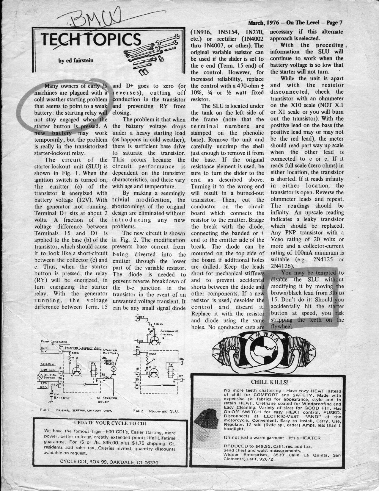
Another possibility is the starter lockout circuit.
Go here to read related headlight information.
Updated 30 March 2023