/5 brake adjustment, and service
This page is about the /5 and newer motorcycles with front drum brakes, from 1970 thru 1977 and the /2 with telescopic forks known as the US models,
For modern linings, or full shoe and backing plate service, I recommend dealing with Vintage Brakes. Michael will take good care of your brake needs.
These various items in this article may seem to be out of order. It has to be that way because each front brake could be in a different condition of repair needed. I suggest that you read the entire article first and this will allow you to make a list as to which items apply to your brake.
The /5 double leading front drum brake is a superb brake. “Leading” is good and “trailing” is not good for braking. When properly adjusted, lubricated, and with a good cable, it stops so well that it is a bit scary to operate. It is, however, sensitive to humidity. The first few uses on a damp morning can easily lock up the wheel. Solution: warm it up by gingerly using it in the first block of riding.
The front brake doesn’t work well when rolling backward. That is because it is double trailing rolling backward.
Front drum brakes
This is where I always start when troubleshooting. Slowly pull the front brake hand lever while watching the right side of the drum brake. A few things should be observed. The two brake arms should move about the same amount. They should move easily and without any jerky motion. The rear arm should move forward first and when it stops, the forward arm should begin to move rearward. You may find that one arm doesn’t move. That arm is sticking due to corrosion and that is not uncommon. Reach down and try to move it by hand away from the other arm.
If you find that the front arm moves first and then the rear arm, that is because the brake springs are installed incorrectly. That is not uncommon. This observation tells you that in order to make the front brake work properly, you must take it apart and assemble it correctly. It probably needs it anyway, so don’t fret.
When the brake backing plate is off, an examination of the front brake springs will show you that they are made of a different diameter wire. The larger diameter wire spring is stronger. The rear arm moves first because it’s spring is weaker. When that shoe contacts the drum, the rear arm stops moving and then the front arm with the stronger spring begins to move. So the two levers move at different times to pull the shoes up against the drum. The cam is the stop or resting point of the lower shoe. This cam determines the distance that you must pull before you start to get brakes. It won’t change the amount of braking action that you get, but it will change the amount of play before you start to get braking.
Just because you find that the arms move freely and in the correct order, don’t start to think that you are home free.
Fixing the front drum brakes
The biggest reason for weak front brakes is that one or both of the shafts that the arms rotate are tight in the bushings. One may remove the shoes and find that the levers seem to move freely. You have already done the hard part by removing the shoes so continue with preventative or corrective maintenance. The shafts must be removed for cleaning and lubrication. Before one removes the arms, refer to the photo #1 below to see if the arms are in the correct position.
 photo #1
If they are, mark the shaft with a punch, as shown in the photo. This will save you some time. See the “alignment” mark at the top of the shaft, right at where the arm has the gap? That way one can reassemble it exactly as it was. If you are not sure that your levers are on in the best place, you can look at these photos to help decide.
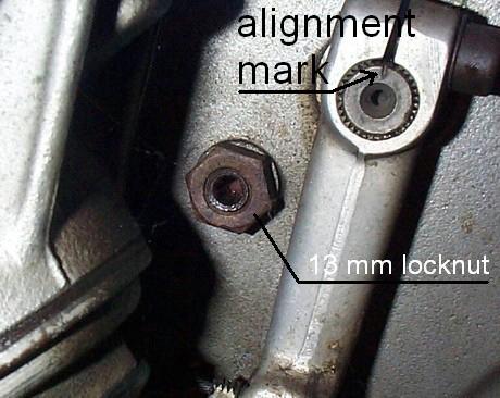 Photo #2
This is the proper angle for the forward brake arm? Photo #2 shows the cam adjustment and 13 mm locking nut.
I suggest that you confirm that the arms are installed correctly first. Then set the front arm travel first. It should have about 3-4 mm (1/8″ to 3/16″) of travel. Don’t obsess over this measurement, as you just may change it later anyway.
To adjust it, you must adjust the stop screw or cam. The adjustment is located just behind and below the forward arm pivot. It is shown above as the “13 mm locknut” in the center of photo #2. Inside it is an Allen screw that uses a 4mm wrench. Loosen the lock nut first. The screw can’t be adjusted due to pressure from the brake shoe. To remove that pressure, reach up and pull the front brake lever with your left hand while you turn the wrench to its limit, with your right hand. Turn the 4mm wrench either way, as it amounts to the same thing. When it comes to a hard stop, back it off a “smidgen” and tighten the lock nut. The thing I can’t tell you is what is a “smidgen.” To test it, pull the brake lever and release it a few times. Check the travel distance of the arm. The wheel should spin freely, which means it has no brake drag. You want the least amount of lever movement that still has no drag of the wheel with brakes off. This will get you very close.
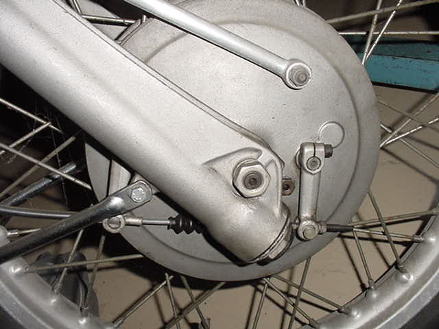 Photo #3
Measure the distance between the two brake arms at the lower end. It should be about 16.5 cm (6 1/2″). If you find it to be about 18 cm (7″) then one or both arms have possibly been repositioned and it was done incorrectly. Put the forward one on in the position shown in the photo above and then the rear arm on last by measuring it. Moving the arm just one tooth on the splined shaft will move the end of the arm by about one cm (almost 1/2″).
Now it is time to set the rear arm travel. It should move about 3-4 mm total. Adjust this with the front brake cable adjuster just to the rear of the rear arm.
When properly positioned, the forward arm will slant backward from vertical just a bit. The rear arm will be at about a 45-degree angle to the ground. The rear arm’s cable barrel will just barely be able to be removed. It wants to interfere with the fender brace slightly. You may see in the photo below that the rear barrel is installed backward. It can’t be removed without first removing the brake arm from the spline on the shaft. This is intentional because it makes it easier to install the cable.
If the correct position of both arms fixes the brakes, you got lucky. This may have been for nothing as you might still need to remove the arms, and shafts from the backing plate to clean and lube. See below for directions.
Installing a new front brake cable on your BMW motorcycle
It is very important to have a fairly new brake cable, as an old cable just might be a major factor in poor braking.
Install the cable at the top end first. Keep in mind that you want all cables to have wide curves to give greater efficiency in applying the desired force. For low bars, thread it down the left side of the headlight shell and cross back to the brake side. Thread it through the rear barrel and attach it to the front lever arm. You will find that it is too short to get the adjustment nut on. The forward lever must be moved back enough (or the rear lever forwards) to get the cable adjuster nut started. I have used three different ways to get the nut started.
First is the slower way, shown below, using a crescent wrench. You must remove the Allen bolt to make room for the wrench. This method seems “nicer” as it greatly reduces the chance of damage to the arm. On a daily runner, it matters none. Use #2 method.
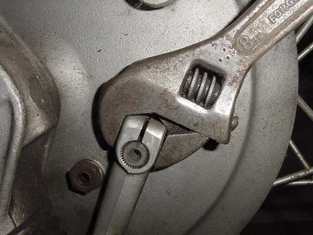 Photo #4
1. Adjusting with a crescent wrench
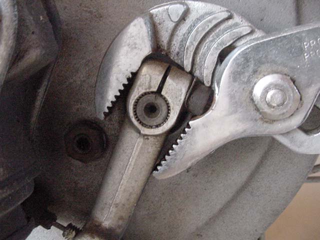 Photo #5
2. The faster way.
To avoid the time to remove and install the bolt, I prefer to do it the faster way shown in Photo #5. I use a piece of leather to protect the forward arm from the jaws of the adjustable pliers. I do not show it here because it obscures the view.
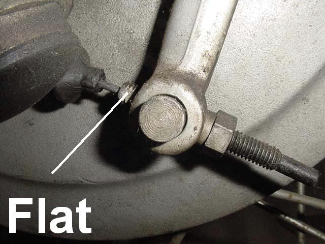 Photo #6
Photo #6 shows one of the two “flats” on the threaded adjuster sleeve. In this photo, the adjuster nut is already on the threaded sleeve, but this is just to show the location of the quite small flats. The flats give a place for a wrench to hold the sleeve so that it can be held while turning the nut.
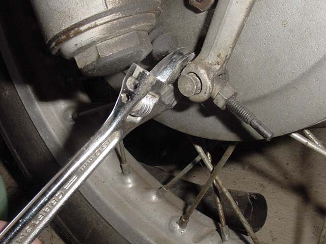 Photo #7
3. Photo #7 shows an adjustable crescent wrench tightened up on the two flats.
By holding the wrench, it is possible to use it to pull forward with your left hand and get enough slack in the cable to start the nut with your right hand.
New linings may not be “worn in” for some time. The important thing is to make sure that you have no brake drag, so test it by spinning the wheel. The amount of lever movement will be more than before because the shoes aren’t touching fully. The cam may need to be adjusted from time to time until the shoes are touching on 100% of the surface. The total play will reduce as you adjust them because the shoes wear in better.
When the brakes are applied, the best mechanical advantage is had when the two lever arms are parallel and at right angles to the cable. You don’t care “much” where they are when the brakes are off. A small error isn’t important. In the off position, they are splayed apart. You can see that they are also a bit that way, even when applied. That is the way that I mount the levers if there is going to be any amount of error. That way, as the linings “wear in” they become more parallel.
Cleaning the shaft and bushing
It isn’t uncommon for one shoe to stop moving entirely and then you have a single leading brake. You may need to perform the steps below.
To remove the brake backing plate one must first remove the brake stay. That is the long slender aluminum arm that keeps the backing plate from turning.
It is a bear to remove the springs/shoes and isn’t even needed to remove the shaft. Use a lever to lift the shoe off of the shoe actuating cam. Then pull the shaft out for cleaning and lube. To clean out the bushing, I used a wooden shaft with a slot cut in the end to hold a piece of sandpaper. I put it in a drill and that quickly cleans out the inside of the bushing. You should use marine grease to lubricate the inside of the bushing, Marine grease will resist being washed away. I also apply some grease to the shaft.
The adjuster stop cam should always be checked for being easily adjusted. It may have to be removed, cleaned, and lubed with grease too.
To install, just reverse the order.
The two levers should swing about the same amount. Adjust until the movement is minimum with no brake drag. When you are finished, the lever should pull in about 1/2 way and come to a quite solid stop. Test it carefully the first time that you test ride it, as it may be quite different than before.
Rear brake repair and adjustment
The purpose of the rear brake is to stop the rear wheel, not to stop the motorcycle. The tire stops the motorcycle and that efficiency depends on the specific tire. If you can’t easily stop the rear wheel with moderate foot pressure, then it needs some attention.
Removing the rear wheel from your BMW motorcycle
This procedure may vary a lot, depending upon year and accessories mounted. A tire that is wider than specified by BMW may make the job harder.
Make sure that the bike is on the center stand and very stable.
Back off a few threads on the swing arm pinch bolt. No need to remove it.
Remove the axle nut and washer.
Use a bar to rotate and pull on the axle. It should come out fairly easily.
You may need to back off on the rear brake adjustment wing nut a bit.
From the left side, you should be able to gently pull on the wheel to get it off of the brake shoes. If the shoes are fairly tight against the drum, you may need to rotate the wheel a lot while pulling it off. What happens is that the shoes can try to go with the wheel. They get cocked a bit and that actually makes them tighter in the drum. Now it won’t move at all. That is why rotating helps.
The wheel should just wiggle out of the area and roll between the fender and muffler. If not, go to the next procedure.
Have a helper tilt the bike over on the right side and hold it. Now the wheel can come out of the bottom and miss the muffler and fender. If no helper is available, then use something to cushion the right side valve cover and lay it over. One may have to let the air out of the tire too.
Inspect the linings for grease. You may get by with washing the grease off, but more heat later from braking may pull more grease out and reduce stopping. If the linings are contaminated with grease, they should be replaced. Be careful about buying a kit for this job, as it may not be the best way to go.
Rear brake linkage
Grab the foot brake lever and wiggle it sideways. It should only have a slight movement. If yours wiggles a lot, it is because of wear caused by a lack of maintenance/lubrication. To remove the brake lever for inspection, cleaning and lubrication, first, back off the rear brake adjustment on the final drive. Run the wing nut back several turns.
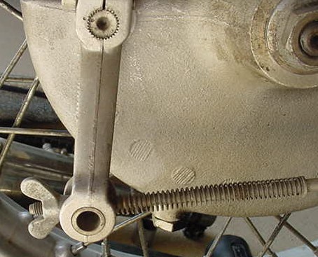 Photo #8
Photo #8 shows that the normal adjustment should look something like this. See the slightly less than a 90-degree angle between the brake arm (vertical part) and the rod (horizontal part) with the spring? When the brake is applied, that angle comes closer to 90 %, which is where one gets the maximum force applied to the brake, depending on the cam wear. See the upper shaft and the two punch marks at about 10 O’clock? I made those punch marks. This allows one to remove and reassemble it in the same position. The arm is mounted on the shaft on splines. There is little variation allowed. You should punch the marks before you remove the arm if you think that the arm is in about the correct spot. This allows you to reinstall the arm in the correct position the first time. This shaft is something that should be removed for cleaning and lubrication. More on that later.
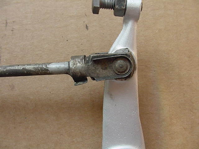 Photo #9
Photo #9 shows what is back behind the driveshaft and is hard to see.
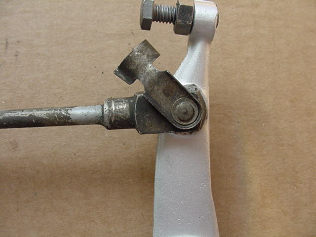 Photo #10
Lift the sheet metal fastener to the position shown in photo #10. It now comes towards you. It will probably be impossible to get out. They get rusted and so I suggest some WD 40 with Silicone or your favorite anti-seize oil. You may even have to punch it out from the other side using something that is long and slender.
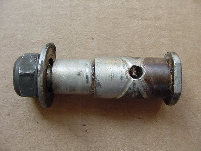 Photo # 11
Photo #11 shows the bolt that you wish to remove. On the right end are two flats for a wrench. Hold the bolt by the flats and remove the nut shown on the left. It is kind of tricky at first to reach both, but it can be done. Examine this bolt. See the hole for grease? See the rust that is to the right of it?
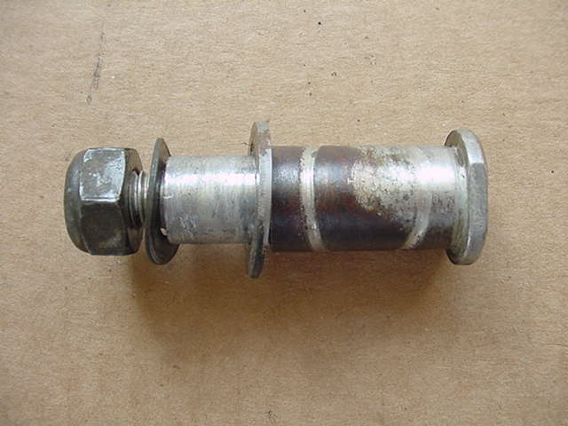 Photo #12
Photo #12 shows the backside. I have cleaned out the grooves for the grease so that they show up well. They are cut in a “spiral” around the bolt. They are not rusted because they had grease in them. The body of the bolt is rusty because it didn’t get greased routinely. As soon as the grease is forced out, the water gets in. The rust now “grinds” away at the tube welded on the frame. The rust causes friction and some braking action is lost due to the rust. The frame tube gets worn larger and the brake lever is now sloppy. You can’t easily fix the part that is now worn, but you can make sure that it doesn’t wear more. The photo above shows the washers in the proper position.
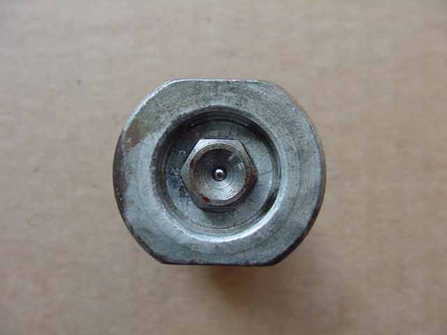 Photo #13
Photo #13 shows the head of the bolt with its grease zerk in the middle. Remove it with a 7 mm socket. Take care not to lose it, as I have no idea where one gets another one.
The old grease can be very hard to get out. Photo #14 shows how I often start with a drill bit and turn it by hand. The flutes allow some of the hard grease a place to go and get pulled out.
Solvent and an old-fashioned Q tip will clean the hole out.
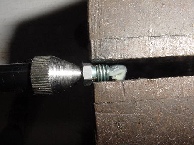 Photo #16
Photo #16 shows that the zerk is held in the vise by the grease gun, not the jaws. This is to test the zerk. You can see some grease that just got pumped through. It must flow freely, or you must replace it.
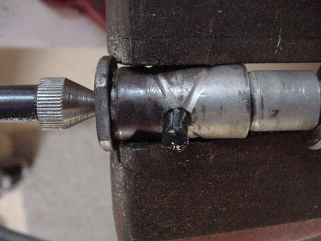 Photo #17
Photo #17 shows that the zerk has been reinstalled and tested. See the grease that was pumped through? Don’t assume that it will work unless you have tested it.
 Photo #18
Photo #18 shows what the lever should look like.
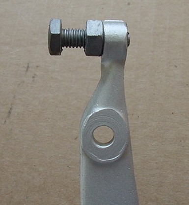 Photo #19
Photo #19 shows the adjuster bolt in about the usual position.
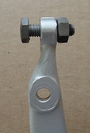 Photo #20
You might need to move the nut around to the other side to get the adjustment as shown in photo #20. That is an unlikely option that is seldom seen and I would be concerned if this is needed. If one is doing something special, then maybe it is OK. On an average bike, this would only be needed if something is bent or altered. I would want to find out why. With the adjuster bolt screwed in this much, the foot brake lever would be raised up a lot. It isn’t unknown for the brake lever to get bent. It usually occurs between the empty hole and the adjuster. They even break off. The part can be welded back on again. The bolt/nut shown serves two purposes, to operate the brake light switch and be a stop for the lever position. By adjusting this bolt, one can move the lever up and down. Your preferred foot and toe position may be improved by this adjustment. Don’t be afraid to play with it a bit. Many of these bikes have never had the lever in the best position for the rider. You may also move the foot pegs up or down to fit your leg length. Any adjustment with these parts will require some adjustment of the wing nut at the final drive.
How to fix the front or rear brake squeal
1. When it is first ridden, especially in the morning or anytime that it has been sitting for 12 hours or more and could have collected humidity. The first few stops will screech and be grabby and hard to control. After those first few stops, everything should seem to work as before.
Solution 1; anticipate this condition and don’t allow yourself to get into a panic stop before you “dry out” the brakes. Don’t try to dry them on a gravel road. Get up to about 25-30 and feather the brakes slightly. Let up when they grab and do it all over again. Each time should get better. Usually, the front is the dangerous one. The rear is less efficient (single leading brake) and is easier to control.
Alternate solution; move to the desert.
2. No matter how long you use the brakes they will squeal. Usually, gently braking is the loudest and hard braking is quiet or not so loud. As you come to a complete stop and let up appropriately, they get louder.
Solution; remove the shoes of the offending brake and chamfer the leading edge. That is, Use a file to bevel it back so that the leading edge isn’t square anymore. Angle it for maybe 1/8″ or so.
You may hear that you should “break the glaze” on the lining surface. To do that you MUST remove the shoes. Lay wet-n-dry dark gray sandpaper on a smooth surface and drag the shoe over it. Don’t hold the shoe and move the paper back and forth over the shoe.
The problem with this solution is that usually it will only stop the squeal for a short time and it will be back. Consider using modern friction material. It might be time to call Vintage Brakes.